


Operating the RGB 320 Panels • Chapter 3
RGB 320 Switching Interface System • User’s Manual • Extron
Controlling the RGB 320 Interface
The RGB 320 can be controlled from the front panel, from an input buffer, from an
external RS-232 device or from Extron’s Windows® based control software. This
includes selecting video, audio or both from one of six inputs, adjusting horizontal
and vertical centering or adjusting the video and audio levels. See Chapter 4 for
Windows® software and Appendix A for RS-232 programming.
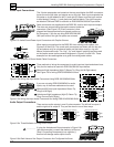
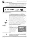
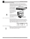
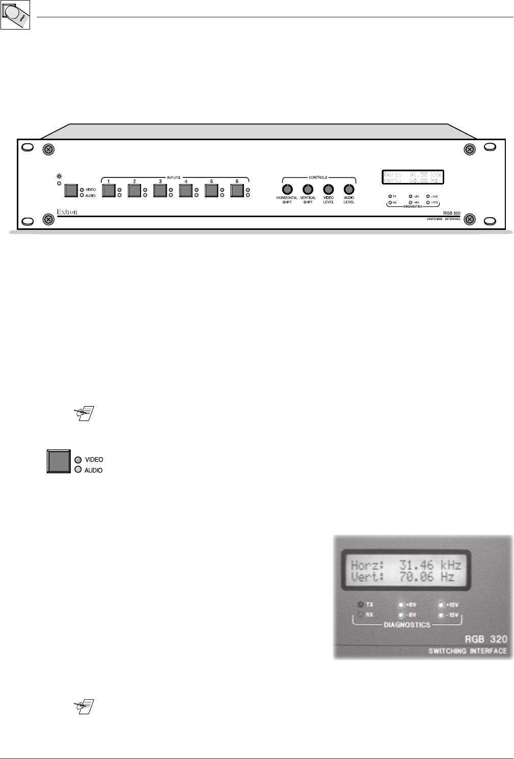
Figure 3-1. The RGB 320 Front Panel
Memory Functions (store/recall/clear)
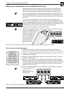
Although the interface functions are processed within the RGB 320, “virtual
interfacing” can be done from an RGB 322, RGB 324 or RGB 340 buffer by
pressing the “Show Me” button on its panel. The button requests that the
RGB 320 display the input signal from that buffer to the output display device(s),
and also initiates communication with the RGB 320 to allow adjustments to be
made from the buffer panel. These include horizontal shift, vertical shift, video
levels and audio levels. See the user’s manual 68-338-01 for details.
Adjustments for all inputs (buffers or other devices) can be made from the front
panel, or from an RS-232 host device. Regardless of where they were made,
these settings are saved in memory blocks associated with each input.
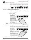
________ Memory blocks for each input can be cleared from the front panel by holding the
Video/Audio button while pressing the Input button for the channel to be reset.
The input LEDs blink and then are steady “on” when memory has been cleared.
When an input is selected, the RGB 320 searches for a configuration that
matches that computer, and it automatically recalls the appropriate video scan
rate. It may not be necessary to recalibrate the settings when a computer is
selected from an input. Ten of the most popular computer scan rates are
permanently programmed into the RGB 320’s memory.
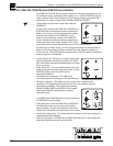
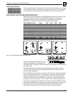
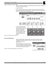
LCD Display
The front panel LCD screen displays
five functions:
• The default display shows the scan rate
for the selected input (if no video is
connected to the selected input, both
frequencies will appear as 00.00)
• Horizontal shift (see page 3-4)
• Vertical shift (see page 3-4)
• Video level (see page 3-4)
• Audio level (see page 3-4)
Figure 3-2. The Front Panel LCD Display
________ When switching from one input to another, regardless of where it is from, the LCD
display blinks while “locking” in on the new input. For RS-232 programming, the
message “reconfig” will appear during this time. If adjustments are made during
this transition time, they may not be stored.
3-1