


Chapter 1 • Introduction to the RGB 320 Switching Interface System
Extron • User’s Manual • RGB 320 Switching Interface System
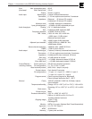
• horizontal shift (from RGB 322, RGB 324 & RGB 340)
• vertical shift (from RGB 324 & RGB 340)
• video level (from RGB 324 & RGB 340)
• audio level (from RGB 324 & RGB 340)
The RGB 320 saves these adjustments in a memory associated with each input.
The RGB 320 has 15 memory blocks for each of the six inputs. The memory
blocks store the picture controls needed for an application or installation. When an
input buffer is selected, with a computer connected, the RGB 320 searches for a
match for that scan rate and automatically recalls the appropriate input settings
for that device. This eliminates having to recalibrate the settings each time a
specific computer is selected. Ten of the most popular computer scan rates are
permanently programmed into the RGB 320’s memory so programming may not
be necessary.
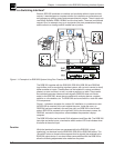
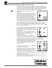
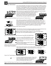
Figure 1-2. The RGB 322 and RGB 324 Can Be Installed in Walls
The RGB 320 has features that help to maintain the original signal integrity and
enhance overall system performance. A video level control is provided to
compensate for weak signal source or signal loss due to cables or other system
components. For example, if the signal from input #1 is weak, this control can
boost it; if the signal from input #3 is strong, it can be attenuated. Each setting is
stored for that input.
The RGB 320 also provides LCD sync processing that ensures a stable image for
LCD and DLP presentation devices.
Controlling the RGB 320 Interface
The RGB 320 can be controlled from front panel control buttons, from the
RGB 322, RGB 324 and RGB 340 buffers with “virtual interfacing” or with Extron’s
Windows® Control Program software. An RS-232 serial port allows control by a
third party control system. Extron’s software allows control of the RGB 320 from a
remote PC with a graphic interface.
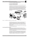
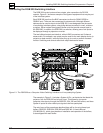
The six inputs to the RGB 320 can originate from remote input buffers or from a
(local) device in the rack, such as another switcher, a line doubler, a dedicated
audio system or a computer interface. The RGB 322, 324, 326 or 340 input
buffers may be located in various places around a room. The RGB 320 switches
the signals to a display device, a system switcher or a line doubler, etc.
1-2