


Operating the RGB 320 Panels • Chapter 3
RGB 320 Switching Interface System • User’s Manual • Extron
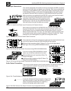
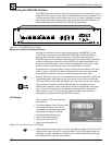
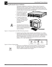
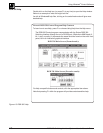
Diagnostic LEDs
The front panel has six diagnostic LEDs. The right-most pair monitor +15 and -15
voltages, and the middle pair monitors +8 and -8 voltages. If any of these four
LEDs are not lit, the system will malfunction.
The left-most pair of LEDs will blink during
RS-232 communication with a controlling
device. Tx is transmit and Rx is receive.
________ Tx blinks each time a panel change has
been completed to notify the host of a
change in status.
Figure 3-10. Six Diagnostic LEDs on the Front Panel
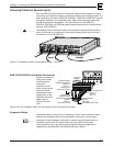
Rear Panel Switches
Switches on the rear panel affect all the video signals that come from the
RGB 320.
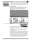
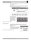
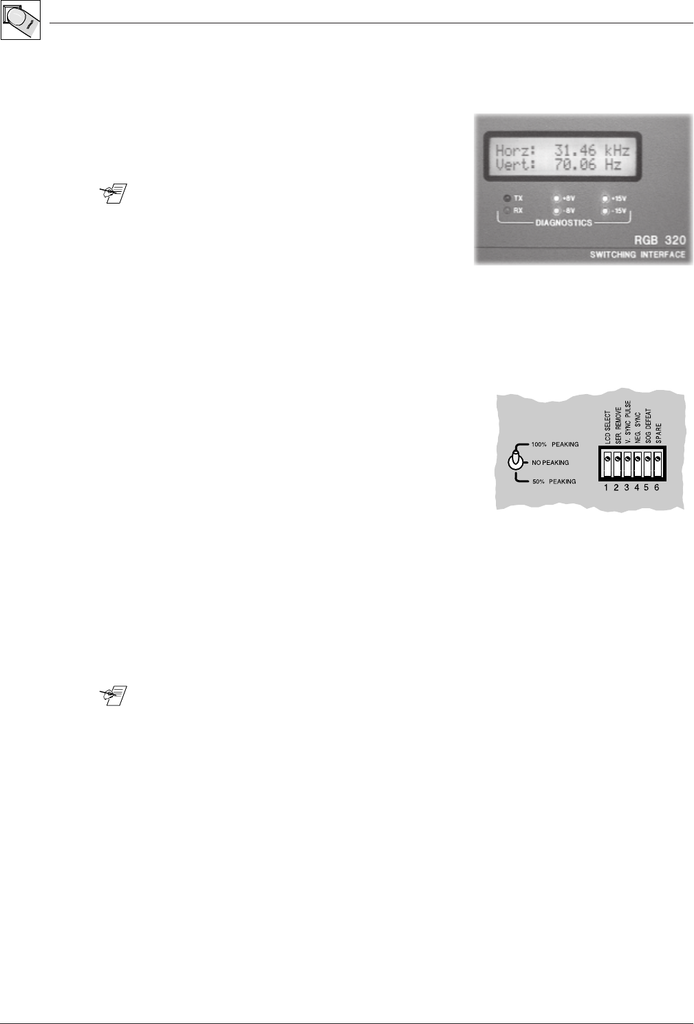
Peaking Switch
To the left of the DIP switches is a three-position toggle switch. If the RGB 320 is
driving long cables, this switch allows
compensation for cable capacitance. The
middle position is Normal and does not alter
the output load. The lower position provides
50% peaking, and the upper position provides
100% peaking. Set the switch in the position
that provides the best image on the output
display device.
Figure 3-11. Peaking Switch and DIP Switches are Located in the Lower-right Section of the Rear Panel
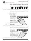
DIP Switches: Sync Options and Serration Pulses
The DIP switches are located in the lower-right section of the rear panel. The
factory settings are all
Off
. Their functions are as follows:
1 LCD Select
Use the on position for an LCD output device or other digital device. In this
position, the horizontal and vertical shift (centering) controls are not active. Use
the off position for non-LCD or analog devices.
________ Because this switch disables the RGB 320 centering controls, when adjusting
centering from the projector, turn this switch on before adjusting the projector’s
centering controls.
2 Ser. Remove
Use the on position to remove serration pulses. In the off position, the RGB 320
will allow serration pulses, or it will add them if they are not already present.
3 V. Sync Pulse
In the on position, this switch increases the width of the vertical sync pulse to
approximately twice its original duration. The actual sync width will depend upon
the frequency of the incoming signal. Use the off position for normal width.
4 Neg. Sync
Use the on position for negative sync. This setting would depend upon the
requirements of the output display device (projector).
5 SOG
In the on position, sync on green is forced. Because the RGB 320 has three BNC
connectors for output sync, there is always one output with composite and two for
separate horizontal and vertical sync.
6 Spare
3-5