


Contents
Extron • User’s Manual • RGB 320 Switching Interface System
Contents
Legend of Icons .................................................................................................................ii
Revision Information ..........................................................................................................ii
Chapter One • Introduction to Switching Interface
What is a Switching Interface? .................................................................................................... 1-1
Function ......................................................................................................................... 1-1
Controlling the RGB 320 Interface.................................................................................. 1-2
Features......................................................................................................................... 1-3
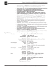
Specifications ................................................................................................................. 1-3
RGB 322, RGB 324, RGB 326 and RGB 340 Input Buffers ........................................................ 1-5
Chapter One • Illustrations
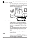
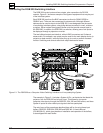
Figure 1-1. Example of an RGB 320 System Using Four Possible Buffer Types Installed in a Conference
Room............................................................................................................................................................ 1-1
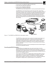
Figure 1-2. The RGB 322 and RGB 324 Can Be Installed in Walls.............................................................. 1-2
Chapter Two • Rear Panel Connections
Connecting the RGB 320 Switching Interface ............................................................................. 2-1
Rear Panel Connectors .................................................................................................. 2-2
Audio Input Connections ................................................................................................ 2-3
Audio Output Connections ............................................................................................. 2-3
Choosing Cables for Remote Inputs ........................................................................................... 2-4
RGB 322/324/326/340 Input Buffer Connections ........................................................... 2-4
Composite Cables .......................................................................................................... 2-4
Buffer Input Cables ........................................................................................................ 2-5
Chapter Two • Illustrations
Figure 2-1. The RGB 320 as a Computer Video Switching Interface to a Line-quadrupling System........... 2-1
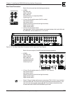
Figure 2-2. The Rear Panel Has Connectors for Six Inputs and Two Outputs ............................................. 2-2
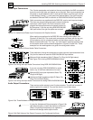
Figure 2-3. Audio/Comm/Power Input Connectors with Captive Screws ..................................................... 2-3
Figure 2-4. Examples of Round Audio Cable Connectors ........................................................................... 2-3
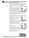
Figure 2-5a. Wiring the Input Audio Connectors Using RGB 324/326/340 Buffers...................................... 2-3
Figure 2-5b. Wiring the Input Audio Connectors Not Using RGB 324/326 Buffers ...................................... 2-3
Figure 2-6a. Three Methods of Wiring Audio Output.................................................................................... 2-3
Figure 2-6b. Both Halves of the Output Connector Are Configured the Same ............................................ 2-3
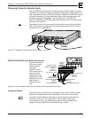
Figure 2-7. Installation Cables Connected to Inputs 1, 3 and 5 ................................................................... 2-4
Figure 2-8. One Installation Cable Can Be Used for Each Input and Each Output ..................................... 2-4
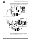
Figure 2-9a. Installation Cable Wired for the RGB 320 ................................................................................ 2-5
Figure 2-9b. Installation Cable Wired for the RGB 322/324/326/340 (RGB 322 Has No Audio) ................. 2-5
Chapter Three • Operating the RGB 320 Panel
Controlling the RGB 320 Interface .............................................................................................. 3-1
Memory Functions (store/recall/clear) ............................................................................ 3-1
LCD Display ................................................................................................................... 3-1
Front Panel Controls ...................................................................................................... 3-2
Using the RGB 320 Front Panel Buttons ..................................................................................... 3-3
Making Input Adjustments from the RGB 320 Front Panel .......................................................... 3-4
Four Video and Audio Adjustments ................................................................................ 3-4
Diagnostic LEDs ............................................................................................................ 3-5
Rear Panel Switches................................................................................................................... 3-5
Peaking Switch .............................................................................................................. 3-5
DIP Switches: Sync Options and Serration Pulses......................................................... 3-5
Chapter Three • Illustrations
Figure 3-1. The RGB 320 Front Panel.......................................................................................................... 3-1
Figure 3-2. The Front Panel LCD Display..................................................................................................... 3-2
i