


Operating the RGB 320 Panels • Chapter 3
RGB 320 Switching Interface System • User’s Manual • Extron
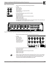
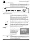
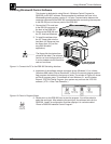
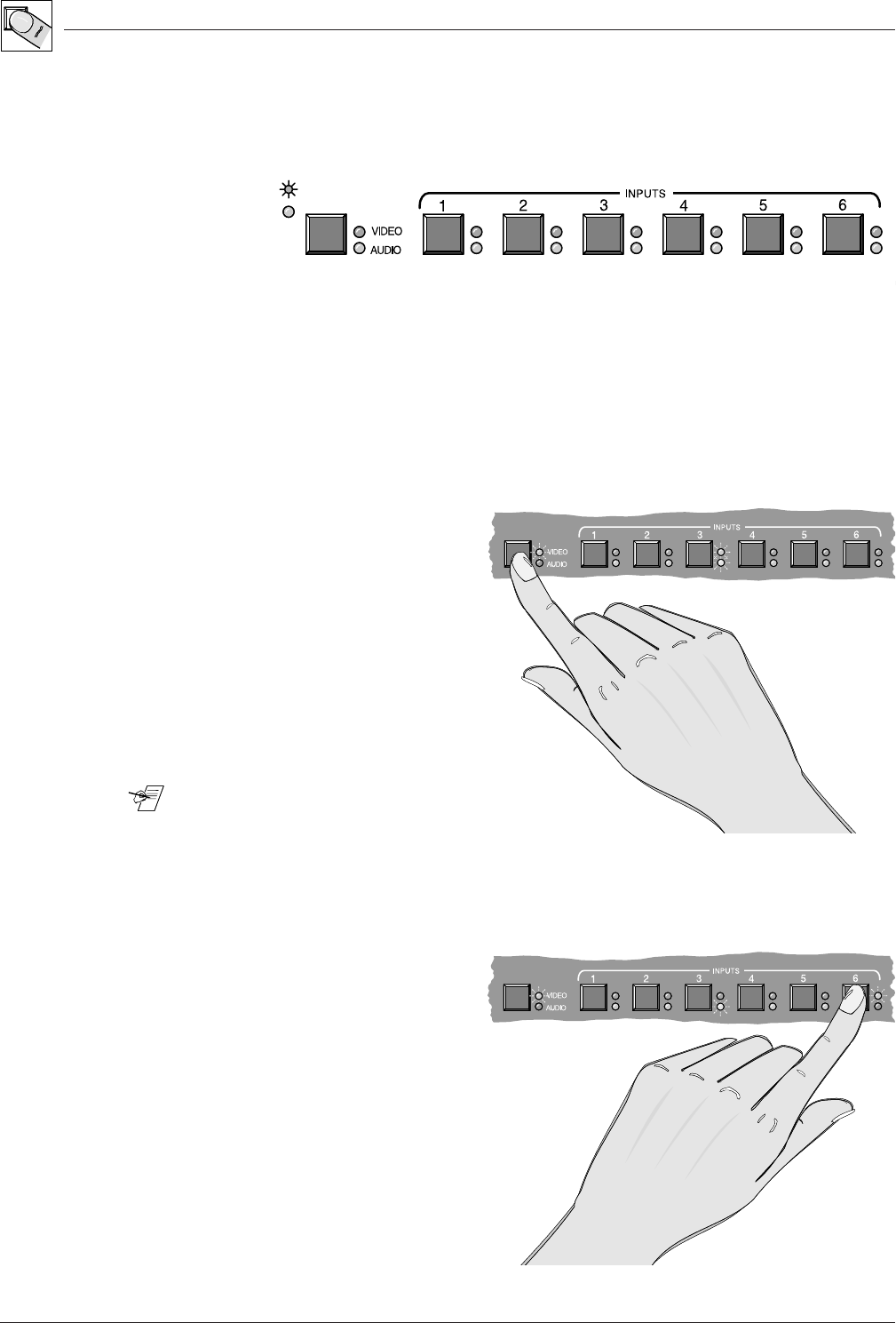
Using the RGB 320 Front Panel Buttons
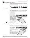
Of the seven buttons on the front panel shown in Figure 3-4, the left-most button
(A/V Mode) determines what will be selected (audio, video or both), and the other
six buttons are used to select an input.
Figure 3-4. RGB 320 Front Panel A/V Mode and Input Selection Buttons
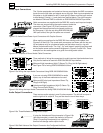
The A/V Mode button has two LEDs next to it. The top one (red) is for video and
the bottom one (green) is for audio. Press the button for one of three modes:
• Video and audio (audio follow)
• Video only (breakaway)
• Audio only (breakaway)
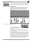
The two LEDs will light
according to the active
mode. Before selecting an
input, if you do not want the
mode that is indicated, press
the button until the LEDs
indicate the mode you want.
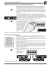
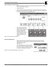
Example: If both LEDs are lit,
both video and audio will be
switched. If you want video only
from input #6, press the mode switch
until the video LED is lit and the audio
LED is unlit. (See Figure 3-5.)
________ This button is also used to clear memory blocks.
See note on Page 3-1.
Figure 3-5. Select the A/V Mode by Pressing the Button on the RGB 320 Front Panel
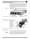
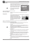
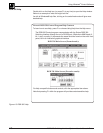
Press the input #6 button. Because you selected the video-only mode, the video
LED #6 (next to button #6) will light, but the audio LED #6 will not light.
When the RGB 320
switches to input #6, the
horizontal and vertical
frequencies for the
computer video from that input will be
displayed in the LCD default screen. (See
Figure 3-7.)
The audio input LED will remain lit for the
last input selected with audio. For this
example, input #3 had been selected
previously, and it had audio; therefore,
the input #3 audio LED will remain
on, as will the input #6 video LED.
Figure 3-6. Select the Desired Input by Pressing Its Button
3-3