


VSW 2VGA A • Installation and Operation
Installation and Operation, cont’d
2-8
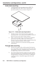
Front Panel Features
VSW 2VGA A
INPUT 1
2
1
INPUT 2
3
5 4 7 6
1
2
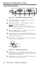
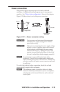
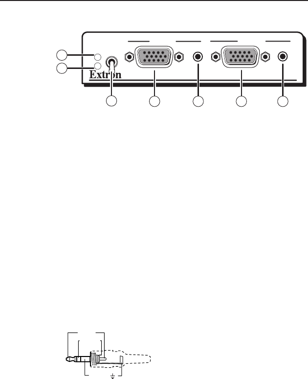
Figure 2-5 — VSW 2VGA A front panel features
a
Input 1 LED indicator — This LED lights green whenever
input 1 (video and audio) is selected.
b
Input 2 LED indicator — This LED lights green whenever
input 2 (video and audio) is selected.
N
The LEDs
a
and
b
above also serve as power up
indicators. When the switcher is powered up, the selected
input's LED lights green.
c
Input select toggle switch — Toggling this switch up selects
input 1; toggling it down selects input 2.
d
Input 1 video — Input VGA-QXGA, RGBHV, RGBS, RGsB,
RsGsBs, component video, or HDTV component video through
this female 15-pin HD connector.
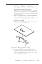
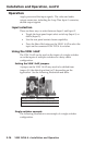
e
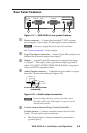
Input 1 audio — Input unbalanced stereo audio through this
3.5mmminiaudiojack(gure2-6).
Sleeve ( )
Ring (R)
Tip (L)
3.5 mm Stereo Plug Connector
(unbalanced)
Figure 2-6 — Audio input connector
f
Input 2 video — Input VGA-QXGA, RGBHV, RGBS, RGsB,
RsGsBs, component video, or HDTV component video through
this female 15-pin HD connector.
g
Input 2 audio — Input unbalanced stereo audio through this
3.5mmminiaudiojack.Seegure2-6.