


VSW 2VGA A • Installation and Operation
2-13
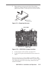
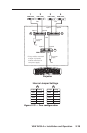
Power connection
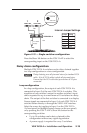
One power supply can power up to five daisy chained
switchers. Additional switchers require one or more power
supplies. See "Daisy chain configuration", later in this chapter.
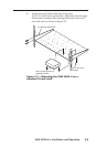
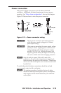
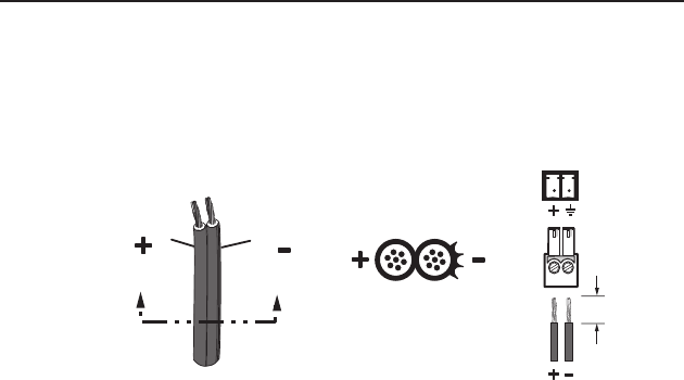
Figure 2-12 shows how to wire the power connector.
Power Supply
Output Cord
Captive Screw
Connector
SECTION A–A
Ridges
Smooth
A A
3/16” (5 mm) Max.
(to ground)
Figure 2-12 — Power connector wiring
C
The two power cord wires must be kept separate
while the power supply is plugged in. Remove
power before wiring.
C
When you are connecting the power supply, voltage
polarity is critical. Applying power with incorrect
voltage polarity could damage the power supply
and the VSW 2VGA A. Identify the power cord
negative (ground) lead by the ridges on the side of
the cord or a black heat shrink wrapping around it.
N
Strip the jacket to expose 3/16 inch (5 mm) of the
conductors. Do not tin the stripped power supply leads
before installing the captive screw connector. Tinned wires
are not as secure in the captive screw connectors and could
be pulled out.
To verify the polarity before connection, check the no load
power supply output with a voltmeter.
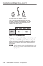
N
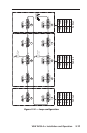
The maximum number of switchers that can be daisy
chained is limited by several factors: power consumption,
cable lengths, and the overall distortion of the video and
audio signals.