


VSW 2VGA A • Installation and Operation
2-9
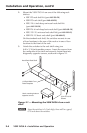
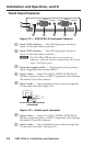
Rear Panel Features
POWER
12V
.1A MAX
VSW 2VGA A
AUTO-SW
CONTACT
OUTPUT
VGA IN 1 LOOP
1 2
AUD OUT
1 5 2 3 4
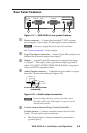
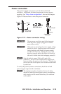
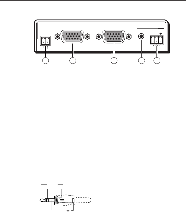
Figure 2-7 — VSW 2VGA A rear panel features
a
Power connector — Connect the included 12 VDC external
power supply to the 2-pole, 3.5 mm captive screw connector.
N
One power supply can power up to five switchers.
See "Power connection" in this chapter.
b
Loop Thru Input 1 connector — female 15-pin HD connector for
buffered local monitor output from Input 1
c
Output — female 15-pin HD connector for output from Input
1 or Input 2. The output video type follows input type and is
either VGA-QXGA, RGBHV, RGBS, RGsB, RsGsBs, component
video, or HDTV component video.
d
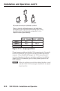
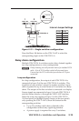
Audio Output connector — Unbalanced stereo audio is output
from this 3.5 mm mini audio jack (figure 2-8).
Sleeve ( )
Ring (R)
Tip (L)
3.5 mm Stereo Plug Connector
(unbalanced)
Figure 2-8 — Audio output connector
N
If you are daisy chaining, connect the other end of
the audio cable to the audio Input 2 connector on the
downstream switcher.
e
Contact closure/Autoswitching (Contact/Auto-SW) —
Contact closure — Connect a contact closure device to this
3-pole, 3.5 mm captive screw connector.
• Pin 1 selects Input 1 when momentarily connected to
ground (pin 3).