


VSW 2VGA A • Installation and Operation
2-15
VSW 2VGA A
Projector
VSW 2VGA A
INPUT 1
2
1
INPUT 2
1 2
Out
VSW I AAP
VSW I AAP
COMPUTER
AUDIO
SHOW ME
VSW I AAP
VSW I AAP
COMPUTER
AUDIO
SHOW ME
Out
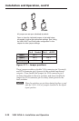
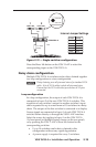
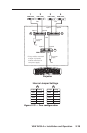
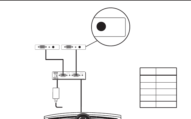
Internal Jumper Settings
Jumper
JMP1
JMP3
JMP4
JMP5
JMP6
Setting
Closed
Closed
Closed
Open
Open
12 V Power
Supply*
Input 1
Input 2
VSW I AAP
SHOW ME
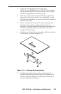
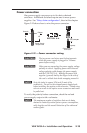
Figure 2-13 — Single switcher configuration
Press the Show Me button on the VSW I AAP to select the
corresponding input on the VSW 2VGA A.
Daisy chain conguration
Multiple VSW 2VGA A switchers can be daisy chained together
in a loop configuration or a tree comfiguration.
N
Daisy chaining uses all pins and wires of a standard VGA
cable. Not all VGA cables include all pins and wires.
Ensure that the VGA cable that you use has all 15 pins
connected.
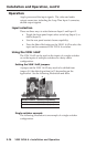
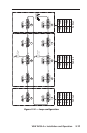
Loop conguration
In a loop configuration, the output of each VSW 2VGA A is
connected to Input 2 of the next VSW 2VGA A switcher. This
repetition of one switcher's output to another switcher's input
can be repeated for up to a maximum of 10 switchers in a daisy
chain. The output of the first switcher is connected to a display.
Source signals are connected to Input 1 of each VSW 2VGA A
switcher either directly or through the VSW I AAP interface.
Select the source by toggling to Input 1 on the VSW 2VGA
A's front panel (or through contact closure on the rear panel)
or by pressing the VSW I AAP's Show Me button for the
corresponding switcher.
• Upto10switcherscanbedaisychainedinthis
configuration without any signal degradation.
• Apowersupplyisrequiredforevery5switchers.