


VSW 2VGA A • Installation and Operation
Installation and Operation, cont’d
2-12
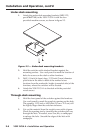
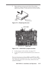
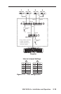
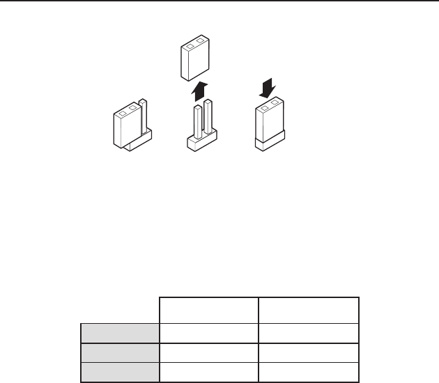
OPEN CLOSED
All jumpers are set open (disabled) by default.
Open or close the indicated jumpers in the table below,
as needed, to adjust the appropriate settings. See “Using
the VSW I AAP” and “Daisy chain configuration” in this
chapter for other jumper settings.
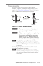
Pin 5 - Control Pin 9 - +5 VDC
Input 1
Input 2
Output
JMP 1
JMP 4
JMP 6
JMP 3
JMP 5
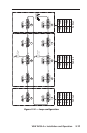
Figure 2-11 — Jumper positions
These jumpers enable or disable VGA connector pin 5 (control)
and VGA connector pin 9 (power) of the switcher inputs and
outputs. Close (install) the jumper for VGA connector pin 5
to daisy chain data to the next switcher, and close (install) the
jumper for VGA connector pin 9 to daisy chain power to the
next switcher.
N
When the switchers are not daisy chained together or used
with the VSW I AAP, all jumpers should be in the default
(open) position.