


VSW 2VGA A • Installation and Operation
2-11
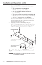
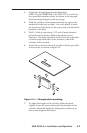
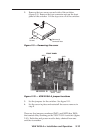
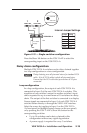
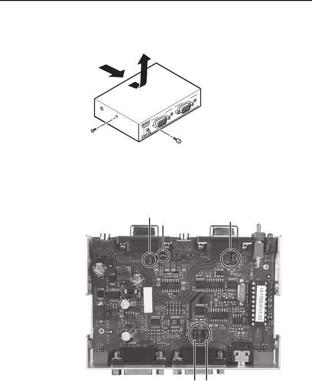
2. Remove the two screws on each side of the switcher
(figure 2-9). Remove the four connector nuts on the front
panel of the switcher. Lift the top cover off of the switcher.
VSW 2VGA A
INPUT 1
2
1
INPUT 2
Remove (4)
Connector Nuts
Remove (4)
Screws
Figure 2-9 — Removing the cover
JMP4
JMP3
JMP5
JMP6
FRONT PANEL
JMP1
EXTRON 20-881-nn x
ER:- yyyyyyyy yyyy
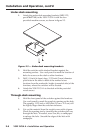
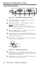
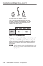
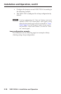
Figure 2-10 — VSW 2VGA A jumper locations
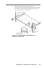
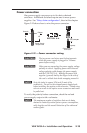
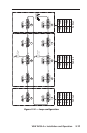
3. Set the jumpers for the switcher. See figure 2-11.
4. Set the cover in place and resinstall the screws remove in
step 2.
Therearevejumpers,numberedJMP1,andJMP3thruJMP6,
that control daisy chaining on the VSW 2VGA A switcher (figure
2-10). Both data and power must be daisy chained from one
switcher to another.