


www.rletech.com 18 970.484.6510
1 System Overview
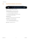
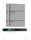
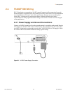
1.4. Rear Panel Indicators
The rear panel of the F3400/F1000 houses a pair of green LEDs. The chart below tracks
indicator status when the corresponding green LED is illuminated:
Figure 1.3
Rear LED Indicator and Status
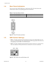
1.5. SW1 Switch Settings
SW1-1: EIA485 Termination switch should be On (down) if the F3400/F1000 is the end
device on an EIA485 network. The switch should in the OFF (up) position if the device is at
the beginning or in the middle of an EIA485 network.
SW1-2: EIA485 Termination switch should be On (down) if the device is connected via a
four wire connection. OFF (up) if the device is connected via a two wire connection.
Figure 1.4
SW1 Switch Is On and SW2 Switch Is Off
Table 1.2
Rear Panel Status Indicators
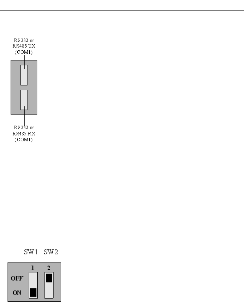
EIA232 or EIA485 TX (COM1) Interface Data is being transmitted.
EIA232 or EIA485 RX (COM1) Interface Data is being received.