2620A, 2625A
Users Manual
2-4
Line Power
Warning
To avoid shock hazard, connect the instrument power cord to a
power receptacle with earth ground.
Plug the line cord into the connector on the rear of the instrument. The instrument
operates on any line voltage between 90 and 264V ac without adjustment, and at any
frequency between 45 and 440 Hz. However, the instrument is warranted to meet
published specifications only at 50/60 Hz.
Front/Rear Panel Features
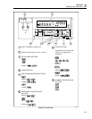
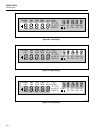
The Front Panel (shown in Figure 2-2) provides a two-terminal input for channel 0, a
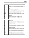
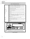
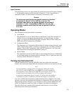
multipurpose display, and a set of control buttons. The display includes the following
elements:
• A major numeric chapter (called the Left Display). See Figure 2-3.
• An auxiliary alphanumeric chapter (called the Right Display). See Figure 2-4.
• A set of Display Annunciators. See Figure 2-5 and Table 2-1.
The buttons control all instrument operations: channel configuration, instrument
configuration, measurement functions, and print/communications selections. The buttons
are introduced in this chapter, with a more detailed description following in Chapter 3.
The Rear Panel (shown in Figure 2-6) provides input and output connections: power
input, measurement input, digital input/output, Totalizer input, alarm output, and
computer interface connections. These connections are introduced in this chapter and
explained in greater detail in subsequent chapters of this manual. Inputs and outputs are
described with their related functions (Measuring DC Voltage, Totalizing, etc.) in
Chapter 3. RS-232 and IEEE-488 Computer Interface connections are detailed in
Chapter 4.


