


Operating the Instrument from the Front Panel
Channel Configuration
3
3-7
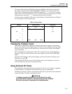
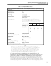
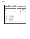
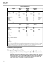
Table 3-3. Resistance
Channel Function
Range
(Note 1)
Terminals
PRESS
THESE
BUTTONS:
TO
SELECT
FROM
THESE
CHOICES:
0
1
.
.
20
OFF
V DC
V AC
Ω
Hz
°C or °F
Auto
300.00 Ω
3.0000 kΩ
30.000 kΩ
300.00 kΩ
3.0000 MΩ
10.000 MΩ
2T
4T
(Completes
Selection
and returns
to Inactive
Mode)
Note 1. Determine the highest resistance value anticipated for this channel. Then select a range large
enough to accommodate this value. If the highest resistance cannot be anticipated, select “Auto”.
Note 2. "4T" allowed on channels 1 through 10 only. For each 4T channel, an additional channel (10
channels higher) is reserved to provide the third and fourth terminals. Channels 11 through 20 are
available for this purpose. Any channel so reserved cannot be used for other definitions.
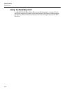
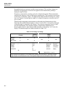
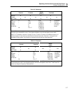
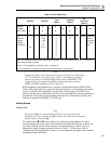
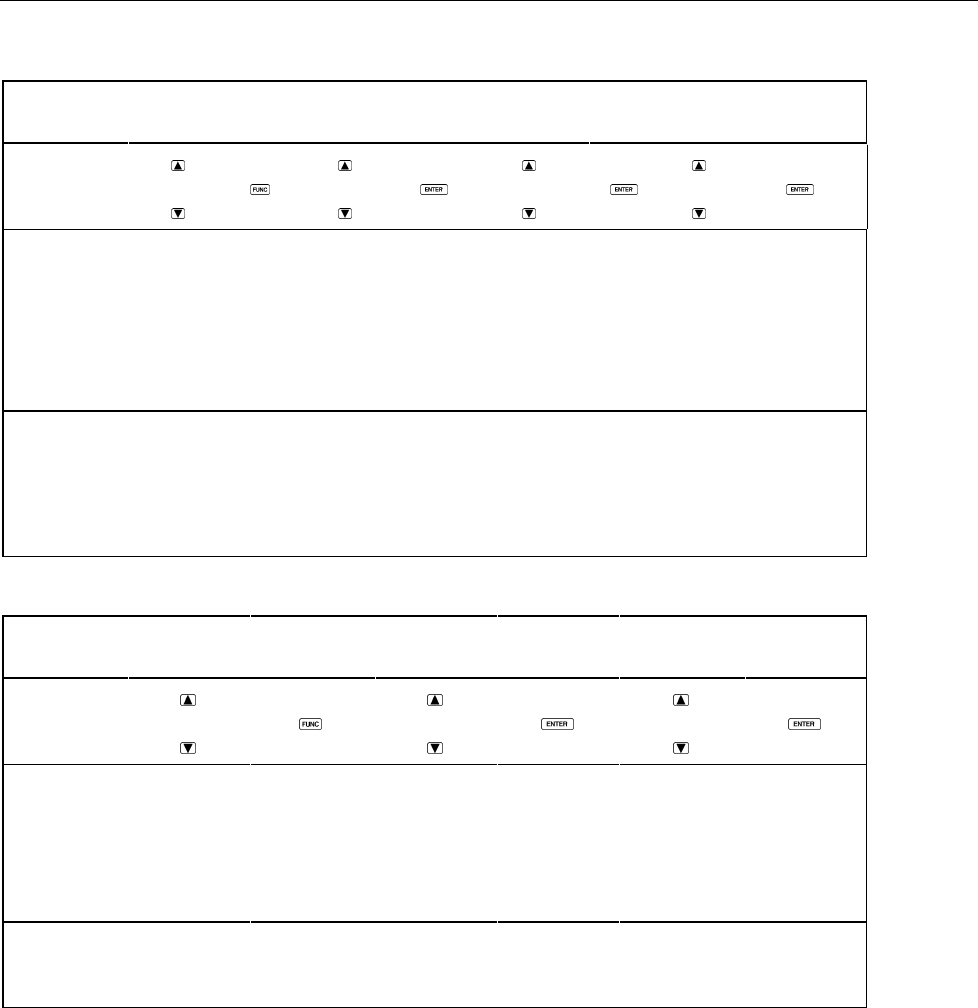
Table 3-4. Frequency
Channel Function
Range
(Note)
PRESS
THESE
BUTTONS:
TO
SELECT
FROM
THESE
CHOICES:
0
1
.
.
20
OFF
V DC
V AC
Ω
Hz
°C or °F
Auto
900.00 Hz
9.0000 kHz
90.000 kHz
900.00 kHz
1.0000 MHz
(Completes
Selection
and returns
to Inactive
Mode)
Note: Determine the highest frequency anticipated for this channel. Then select a range large enough to
accommodate this value. If the highest frequency cannot be anticipated, select "Auto". "Auto" does not
cause any delays for frequency measurements.