Maintenance
Performance Test
6
6-29
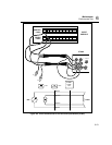
2. Connect Test Leads At the DIGITAL I/O connector, connect the Σ
(Totalizer) test lead and GND test lead to a signal generator’s output
terminals. Adjust the signal generator for an output of 1.5V rms sine wave at
10 Hz.
3. Open Spy Window Select the Spy command from the Utilities menu. Select
01TOTAL. Click OK to open the Spy window.
4. Verify Totalizer Count The Spy window displays the Totalizer count.
Verify the totalizer count is advancing at approximately 10 counts per spy
window update (nominal 1 second intervals).
5. Close Spy Window.
Master Alarm Output Test 6-30.
This test checks the Master Alarm output for a logic low when a channel is in
alarm.
1. Connect Test Leads to ALARM/TRIGGER I/O Connector Remove the
8-position ALARM/TRIGGER I/O connector from the instrument rear panel.
Connect a test lead to each line, MA (Master Alarm), TO (Trigger Output), TI
(Trigger Input), plus a test lead to the GND line. (See Figure 2-6.) Reinstall
the connector.
2. Measure MA Line Using a digital multimeter, measure the output of the
unset MA test lead, referenced to the GND test lead, for a voltage greater than
+3.8V dc.
3. Verify Configuration Channel 1 for Volts DC In NetDAQ Logger, verify
channel 1 is configured for Volts dc, 3V range. (See “Configuring Analog
Channel Functions" in Chapter 3 of this manual.)
4. Verify Configuration Channel 1 for Alarms In NetDAQ Logger, verify
channel 1 is configured for an Alarm 1 with Alarm Sense=LO, Alarm
Value=1 and Digital Output=DO0. (See "Configuring Alarms” in Chapter 3 of
this manual.)
5. Start Instrument Scanning Click the Start Instrument button on the Button
Bar to start instrument scanning. Scanning is initiated to enable the Master
Alarm output.
6. Measure MA Line Using a digital multimeter, measure the output of the set
MA test lead, referenced to the GND test lead, for a voltage less than
+0.8V dc.
7. Stop Scanning Select Logging | Stop Instrument to stop instrument scanning.


