


FortiGate-5140 chassis FortiGate-5140 chassis back panel
FortiGate-5000 Series Introduction
01-30000-83466-20090108 21
http://docs.fortinet.com/ • Feedback
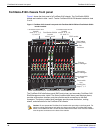
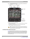
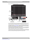
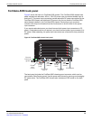
Figure 4: FortiGate-5140 chassis back panel
If you require redundant power you should connect both PEMs to DC power. If redundant
power is not required, you should connect PEM A to DC power. Each PEM has four
-48V/-60 VDC connectors and 4 RTN connections. All eight of these connectors should be
connected to DC power. Figure 4 on page 21 shows the terminal block cover removed
from PEM A and the wiring required to connect PEM A to DC power. While operating the
FortiGate-5140 both terminal block covers should be installed.
The power entry modules are hot swappable, which means you can remove and replace a
defective PEM while the FortiGate-5140 is operating assuming that the FortiGate-5140
system has both PEMs connected to DC power for redundancy.
The back panel also includes the back cable tray, an ESD socket and the chassis ground
connector. The ground connector must be connected to Data Center ground. Use the back
cable tray for securing and managing DC power, RTN, and ground wires.
1 2 3 4 1 2 3 4
HS
HS
operate
Alarm
1 2 3 4 1 2 3 4
HS
HS
operate
Alarm
RTN
1 2 3 4 1 2 3 4
-48V/-60 VDC nom RTN
1 2 3 4 1 2 3 4
Power
Entry Module A
Power
Entry Module B
(terminal block
cover removed)
-48V/-60 VDC
nom (black)
-48V/-60 VDC
nom (black)
RTN
(red)
RTN
(red)
Back cable
tray
B PEM
A
PEM
TERMINAL BLOCK COVER
Remove terminal block cover and
decable before removing PEM.
Chassis
ground
connector
(green)
RTM
slot filler
panels