


FortiGate-5050 front panel FortiGate-5050 chassis
FortiGate-5000 Series Introduction
28 01-30000-83466-20090108
http://docs.fortinet.com/ • Feedback
FortiGate-5050 front panel
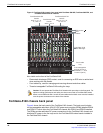
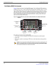
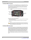
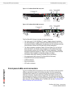
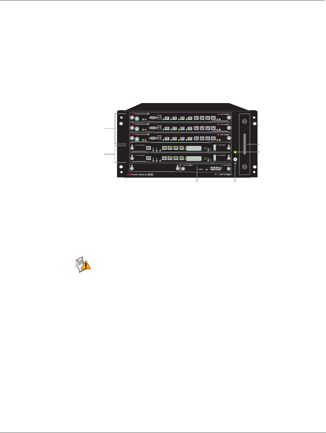
Figure 7 shows the front of a FortiGate-5050 chassis. Two FortiSwitch-5003 boards are
installed in slots 1 and 2. Three FortiGate-5001SX boards are installed in slots 3, 4, and 5.
The FortiGate-5050 primary Shelf Manager is also visible. The factory-installed shelf
managers provide power distribution, cooling, alarms, shelf status, and a telco alarm
interface for the FortiGate-5050 chassis.
Figure 7: FortiGate-5050 front panel with FortiGate-5001SX and FortiSwitch-5003 boards
installed
Also visible on the front of the FortiGate-5050:
• Electrostatic discharge (ESD) socket, used for connecting an ESD wrist or ankle band
when working with the chassis.
• The location of the hot swappable FortiGate-5050 cooling fan tray behind panel.
• Power LED.
FortiGate-5050 back panel
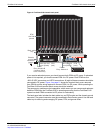
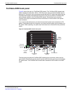
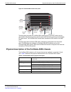
Figure 8 shows the back panel of a FortiGate-5050 chassis. The back panel includes two
redundant -48V to - 58V DC power input connectors labelled Input A and Input B. The
power input connectors provide redundant DC power connections for the FortiGate-5050
chassis and distribute DC power to the fan tray and the FortiGate-5000 series boards
installed in the FortiGate-5050 chassis. Each power input connector includes a 24 Amp
circuit breaker that also functions as an on/off switch for the power input connector.
If you require redundant power you should connect both power input connectors to DC
power. If redundant power is not required, you should connect power input connector A to
DC power. When operating, the power input connectors are covered with clear protection
plates.
1
2
2
3
4
5
ShMC
1
ShMC
POWER
Hot Swap
Status
Alarm
Minor
Console Ethernet
Alarm
Reset
Critical
Major
MANAGEMENT
SYSTEM
E1
ZRE
LED MODE
1514
1312
1110
98
76
54
32
10
E2
OKCLK
INTEXT
FLT
HOT SWAP
RESET
FLT
CONSOLE
E
T
H
O
R
S
2
3
2
Z
R
E
0
Z
R
E
1
Z
R
E
2
MANAGEMENT
SYSTEM
E1
ZRE
LED MODE
1514
1312
1110
98
76
54
32
10
E2
OKCLK
INTEXT
FLT
HOT SWAP
RESET
FLT
CONSOLE
E
T
H
O
R
S
2
3
2
Z
R
E
0
Z
R
E
1
Z
R
E
2
PWR
STAIPM
CONSOLE
USB
1 2 3 4 5 6 7 8
ACC
PWR
STAIPM
CONSOLE
USB
1 2 3 4 5 6 7 8
ACC
PWR
STAIPM
CONSOLE
USB
1 2 3 4 5 6 7 8
ACC
Hot-swappable
cooling fan tray
FortiGate-5001SX
boards
slots 3, 4,
and 5
FortiSwitch-5003
boards
slots 1 and 2
FortiGate-5050
Shelf Manager
ESD socket
Power LED
Caution: Do not operate the FortiGate-5050 chassis with open slots on the front panel. For
optimum cooling performance and safety, the slots must contain a FortiGate-5000 series
board or an air baffle slot filler. As well the removable power supply panel must be installed
over the power connectors on the back of the chassis.