


FortiGate-5000 Series Introduction
50 01-30000-83466-20090108
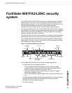
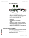
Front panel LEDs and connectors FortiGate-5001SX security system
The FortiGate-5001SX board ships with two RAM DIMMs installed on the
FortiGate-5001SX circuit board. You should confirm that the RAM DIMMs are
installed correctly before inserting the FortiGate-5001SX board into a chassis.
Front panel LEDs and connectors
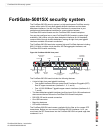
From the FortiGate-5001SX font panel you can view the status of the front panel
LEDs to verify that the board is functioning normally. You also connect the
FortiGate-5001SX board to your network through the front panel ethernet
connections. The front panel also includes the RS-232 console port for connecting
to the FortiOS CLI and a USB port. The USB port can be used with a Fortinet USB
key. For information about using the FortiUSB key, see the FortiGate-5000 Series
Firmware and FortiUSB Guide.
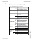
LEDs
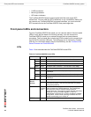
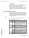
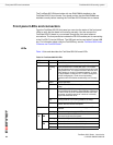
Table 14 lists and describes the FortiGate-5001SX board LEDs.
Table 14: FortiGate-5001SX LEDs
LED State Description
PWR Green The FortiGate-5001SX board is powered on.
ACC Off or
Flashing
red
The ACC LED flashes red when the FortiGate-5001SX
board accesses the FortiOS flash disk. The FortiOS
flash disk stores the current FortiOS firmware build and
configuration files. The system accesses the flash disk
when starting up, during a firmware upgrade, or when
an administrator is using the CLI or GUI to change the
FortiOS configuration. Under normal operating
conditions this LED flashes occasionally, but is mostly
off.
STA Green Normal operation.
Red The FortiGate-5001SX is starting or a fault condition
exists.
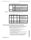
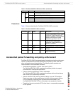
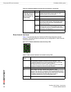
IPM Blue The FortiGate-5001SX is ready to be hot-swapped
(removed from the chassis). If the IPM light is blue and
no other LEDs are lit the FortiGate-5001SX board has
lost power, possibly because of a loose or incorrectly
aligned left extraction lever.
Flashing
Blue
The FortiGate-5001SX is changing from hot swap to
running mode or from running mode to hot swap.
Off Normal operation. The FortiGate-5001SX board is in
contact with the chassis backplane.
1, 2, 3, 4 Green The correct cable is connected to the gigabit SFP
interface.
Flashing Network activity at the gigabit SFP interface.
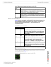
5, 6,
7, 8
Link
LED
Green The correct cable is inserted into this interface and the
connected equipment has power.
Flashing Network activity at this interface.
Speed
LED
Green The interface is connected at 1000 Mbps.
Amber The interface is connected at 100 Mbps.
Unlit The interface is connected at 10 Mbps.