


FortiGate-5050-R chassis FortiGate-5050 back panel
FortiGate-5000 Series Introduction
01-30000-83466-20090108 25
http://docs.fortinet.com/ • Feedback
FortiGate-5050 back panel
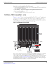
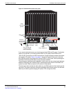
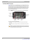
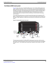
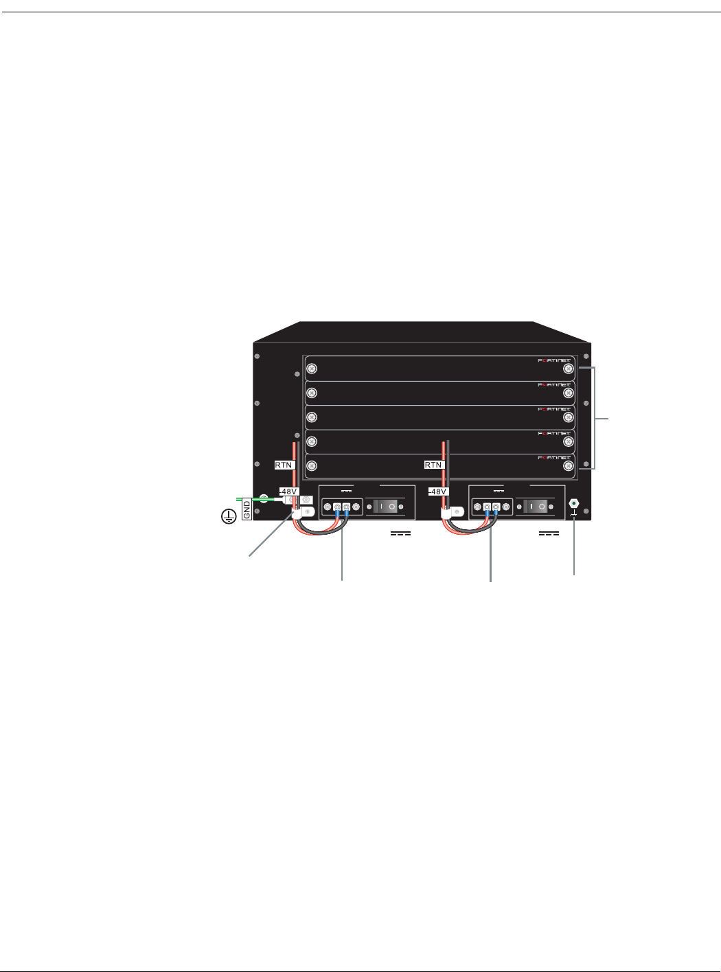
Figure 6 shows the back of a FortiGate-5050 chassis. The FortiGate-5050 chassis back
panel includes two redundant -48V to - 58V DC power input connectors labelled Input A
and Input B. The power input connectors provide redundant DC power connections for the
FortiGate-5050 chassis and distribute DC power to the fan tray and the FortiGate-5000
series boards installed in the FortiGate-5050 chassis. Each power input connector
includes a 24 Amp circuit breaker that also functions as an on/off switch for the power
input connector.
If you require redundant power you should connect both power input connectors to DC
power. If redundant power is not required, you should connect power input connector A to
DC power. When operating, the power input connectors are covered with clear protection
plates.
Figure 6: FortiGate-5050 chassis back panel
The back panel includes the FortiGate-5050 chassis ground connector which must be
connected to Data Center ground. Use the power wire fixtures for securing and managing
DC power wires. The FortiGate-5050 chassis also includes an ESD socket on the back
panel.
5
4
3
2
1
-48V
(-DC in)
(black)
DC Power
Input A
Power
wire
fixture
DC Power
Input B
-48V
(-DC in)
(black)
Positive
(RTN)
(red)
Positive
(RTN)
(red)
INPUT B
24
AMP
-48V
RTN (-DC IN)
INPUT A
24
AMP
ESD socket
Ground
Connector
(green)
-48V
RTN (-DC IN)
RTM
slot filler
panels