


FortiGate-5000 Series Introduction
74 01-30000-83466-20090108
Front panel LEDs and connectors FortiController-5208 system
• Inserting a FortiController-5208 module into a chassis
• Removing a FortiController-5208 module from a chassis
• Troubleshooting
Front panel LEDs and connectors
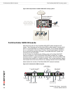
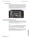
From the FortiController-5208 front panel you can view the status of the board
LEDs to verify that the board is functioning normally. LEDs also indicate
connections and traffic for the front panel and backplane interfaces. You also
connect the FortiController-5208 board to your network through the front panel
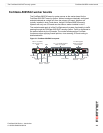
XFP and SFP connections. The front panel also includes two RJ-45 serial console
ports for connecting to the FortiController-5208 CLI and an Ethernet RJ-45 port for
connecting to the CLI and GUI management interfaces over a network.
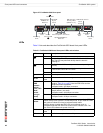
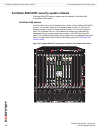
Figure 34: FortiController-5208 front panel
LEDs
Table 25 lists and describes the FortiController-5208 board LEDs.
PAYLOAD OPERATION
STATUS
IPM
X 1
X 2
1/2 3/4 D15/D16 C15/C16
1
2
3
4
5
6
7
8
9
10
11
12
D
13
14
15
16
D
1
2
3
4
5
6
7
8
9
10
11
12
C
13
14
15
16
C
10/100/1000 MBPS ETHERNET ACTIVITY
DATA CONTROL
1
2
3
4
MANAGEMENT
COM 1 COM 2
X 1 X 2
SFP Gigabit
Fiber or Copper
1
3
42
Management
RJ-45 Serial
Extraction
Lever
IPM
Status
X1 X2 XFP 10 Gigabit
Fiber or Copper
Payload
Operation
Link/
Traffic
Extraction
Lever
Mounting
Knot
Mounting
Knot
Link/Traffic
D15
D16
C15
C16
Management
RJ-45 Ethernet
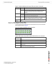
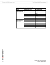
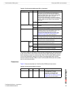
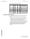
Table 25: FortiController-5208 board LEDs
LED State Description
X1, X2 Green The correct cable is connected to the 10 gigabit
XFP interface.
STATUS Off The STATUS LED is always off, even when the
FortiController-5208 board is starting or operating
normally.
PAYLOAD OPERATION Green
DATA 1-16 Green The data LEDs display base backplane connections
of the FortiController-5208 board and the 5005
boards, over which the load-balanced traffic is sent.
LED 1 corresponds to the FortiController-5208
board’s connection, LEDs 3 through 14 are for
connections to the corresponding slots in a 5050 or
5140 chassis. LEDs 15 and 16 are for the HA ports
D15/D16 on the front panel. Due to the organization
of the backplane, LED 2 will always be off, even if
an operating FortiController-5208 is in slot 2.