


FortiGate-5000 Series Introduction
58 01-30000-83466-20090108
FortiSwitch-5003A configurations FortiSwitch-5003A system
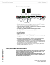
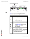
Front panel connectors
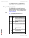
Table 20 lists and describes the FortiSwitch-5003A front panel connectors.
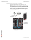
FortiSwitch-5003A configurations
You can operate the FortiSwitch-5003A board as a fabric and base channel
layer-2 switch for any FortiGate-5000 board. The FortiSwitch-5003A board is
compatible with all FortiGate-5000 boards.
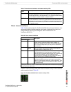
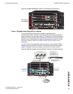
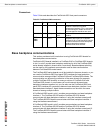
Base and fabric gigabit switching within a chassis
Figure 24 shows a FortiGate-5050 chassis with a FortiSwitch-5003A board in
slot 1 and two FortiGate-5001A boards in slots 3 and 4. In this configuration the
FortiGate-5001A boards are using base channel 1 for HA heartbeat
communication. The FortiGate-5001A boards use base1 as the HA heartbeat
interface.
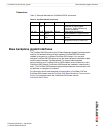
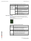
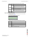
Table 19: Fabric network activity LEDs
Fabric network
activity LED
Interface or connection
2/1 Fabric channel connection between fabric channel 1 and fabric
channel 2. This LED is lit if there are two FortiSwitch-5003A boards
installed in the chassis to indicate fabric backplane communication
between them.
3 to 13 Fabric backplane connection to FortiGate-5000 boards in chassis slots
3 to 13.
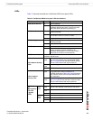
Table 20: FortiSwitch-5003A connectors
Connector Type Speed Protocol Description
MGMT RJ-45 10/100/1000
Base-T
Ethernet Copper gigabit connection to out of band
management interface.
COM RJ-45 9600 bps
8/N/1
RS-232
serial
Serial connection to the command line
interface.
B1, B2 RJ-45 10/100/1000
Base-T
Ethernet Copper gigabit connection to the base
backplane channel.
BASE 10G SFP+ 10 Gbps Ethernet SFP+ 10 gigabit connection to the base
backplane channel.
FABRIC
10G, 14/F8,
F7, F6, F5,
F4, F3, F2,
F1
SFP+ 10 Gbps Ethernet SFP+ 10 gigabit connection to the fabric
backplane channel.