


FortiGate-5000 Series Introduction
32 01-30000-83466-20090108
FortiGate-5020 back panel FortiGate-5020 chassis
FortiGate-5020 back panel
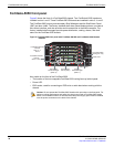
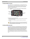
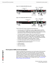
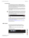
Figure 10 shows the back of a FortiGate-5020 chassis. The chassis back panel
includes two redundant AC power connectors and provides access to the hot
swappable cooling fan tray. Each AC power connector includes a 25 Amp circuit
breaker that also functions as the on/off switch for the AC power connector. You
can use the power wire fixtures to secure AC power wires to prevent the power
wires from being accidently disconnected.
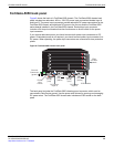
Figure 10: FortiGate-5020 chassis back panel
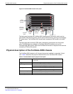
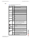
Physical description of the FortiGate-5020 chassis
The FortiGate-5020 chassis is a 4U chassis that can be installed in a standard
19-inch rack. Table 6 describes the physical characteristics of the FortiGate-5020
chassis.
Hot swappable
cooling fan tray
Power
wire
fixture
Power
wire
fixture
AC power
connector
Circuit
breaker
AC power
connector
Circuit
breaker
Table 6: FortiGate-5020 physical description
Dimensions 5.25 x 17 x 15.5 in. (13.3 x 43.2 x 39.4 cm)
(H x W x D)
Weight 35.5 lb. (16.1 kg)
Operating environment Temperature: -13 to 158 °F (-25 to 70°C)
Relative humidity: 5 to 95% (Non-condensing)
Storage environment Temperature: -20 to 80°C
Relative humidity: 5 to 95% (Non-condensing)
Power dissipation Maximum: 800 watts
Power input 2x redundant 110 to 250 VAC