


White Paper Issue: October 2006 Integration of BX600 SB9 Switches in Cisco Networks Page 31 / 47
2.6 Link State
2.6.1 Introduction
BX600 Blade Servers are equipped with 2 independent LAN ports by default. LAN Port redundancy is realized by utilizing NIC
management programs with LAN teaming functions such as ‘Broadcom BACS’, ‘Intel ProSETII’ and ‘Linux Channel Bonding’.
However the server blade cannot detect a link down situation or a port failure situation timely if link failures occur on the uplink
port(s) on SB9 Switch connected to the next higher level switches. In this case, it takes a long time (over 5-10 seconds) to
perform a NIC failover via the teaming software of the server blade (it depends on polling period implemented in NIC
management program). In order to realize a “rapid” fail-over of redundant blade server LAN ports, SB9 is able to shut down
ports linked to server blades (internal ports) whenever an uplink port (external port) fails. If the upstream port is resumed to
active state, the downstream ports will be enabled again.
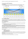
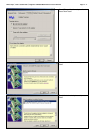
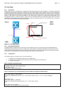
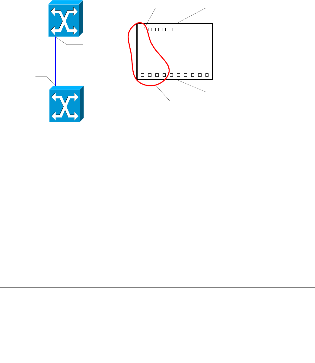
Gi 0/1
0/11
SB9
Cisco
external Ports
internal Ports
link state group
0/11
SB9
detail
downlinks
uplinks
Figure 12 : Link State Group
2.6.2 Recommended Solution
The SB9 provides a monitor task to see the link level of the upstream ports. If any upstream port fails, SB9 will disable the
downstream ports belonging to the same Link State Group. This enables the LAN Teaming Software to detect the link failure
and to switch the LAN port from failed one (Link down) to a working one in a short time. We recommend configuring link state
groups for the considered ports in the customer configuration to improve failover behaviour
2.6.3 Configuration
The following steps are necessary to set up a Link State Group:
• 1. Enable the Link State feature and create a Link State Group
• 2. Configure the up- and downstream ports and enable the configured Link State Group
• 3. Verify the configuration
Step 1: Configure a Link State Group
link state
! Enables the Link State admin mode
link state group
! Creates a link state group
Step 2: Configure the up- and downstream ports and enable the configured Link State Group
interface range 0/1 – 0/4
link state group 1 downstream
! Sets the downstream port(s) for a Link State Group (Port 1 to 4 in this example)
exit
interface 0/11
link state group 1 upstream
! Sets the monitored upstream port for a Link State Group
exit
link state group enable 1
! Enables the configured Link State Group