


Contents
C141-E252 11
Illustrations
Figures
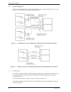
Figure 1.1 Example of SAS system configuration (Dual port internal
cabled environment) ...................................................................... 18
Figure 1.2 Example of SAS system configuration (Dual port internal
backplane environment) ................................................................ 18
Figure 3.1
Cylinder configuration................................................................... 28
Figure 3.2 Spare area in cell ........................................................................... 30
Figure 3.3 Alternate cylinder.......................................................................... 30
Figure 3.4 Track format .................................................................................. 31
Figure 3.5 Track skew/head skew................................................................... 32
Figure 3.6 Sector format ................................................................................. 32
Figure 3.7 Alternate block allocation by FORMAT UNIT command............ 37
Figure 3.8 Alternate block allocation by REASSIGN BLOCKS
command ....................................................................................... 38
Figure 4.1
Dimensions.................................................................................... 42
Figure 4.2 HDD orientations........................................................................... 43
Figure 4.3 Mounting frame structure example ............................................... 44
Figure 4.4 Limitation of side-mounting.......................................................... 45
Figure 4.5 Surface temperature measurement points ..................................... 46
Figure 4.6 Current waveform (Spin-up) ........................................................ 48
Figure 4.7 Current waveform (Max seek)...................................................... 49
Figure 4.8 AC noise filter ............................................................................... 50
Figure 4.9 Connector location......................................................................... 50
Figure 4.10 SAS plug connector overview....................................................... 51
Figure 4.11 Recommended external circuit for Ready LED output................. 53
Figure 6.1
Test flowchart................................................................................ 72
Figure 6.2 Unitary packaging ......................................................................... 77
Figure 6.3 Multi box packaging...................................................................... 78
Figure 6.4 Fraction packaging ........................................................................ 79
Figure 7.1
Sense data format .......................................................................... 82