


Installation Requirements
52 C141-E252
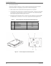
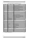
Table 4.2 Interface connector (SAS plug) signal allocation:CN1
Pin No. Signal Description
S1 GND GND for SAS Primary Port
S2 RP+ SAS Primary Port Receive (positive) signal
S3 RP- SAS Primary Port Receive (negative) signal
S4 GND GND for SAS Primary Port
S5 TP- SAS Primary Port Transmit (negative) signal
S6 TP+ SAS Primary Port Transmit (positive) signal
S7 GND GND for SAS Primary Port
S8 GND GND for SAS Secondary Port
S9 RS+ SAS Secondary Port Receive (positive) signal
S10 RS- SAS Secondary Port Receive (negative) signal
S11 GND GND for SAS Secondary Port
S12 TS- SAS Secondary Port Transmit (negative) signal
S13 TS+ SAS Secondary Port Transmit (positive) signal
S14 GND GND for SAS Secondary Port
P1 (*1) Reserved (not used) Not used
P2 (*1) Reserved (not used) Not used
P3 (*1) Reserved (not used) Not used
P4 GND GROUND
P5 GND GROUND
P6 GND GROUND
P7 +5V-Charge Pre-charge pin for +5V
P8 +5V +5V power supply input
P9 +5V +5V power supply input
P10 GND GROUND
P11 READY LED READY LED output
P12 GND GROUND
P13 +12V-Charge Pre-charge pin for +12V
P14 +12V +12V power supply input
P15 +12V +12V power supply input
(*1) P1 to P3 are 3.3V power supply input and pre-charge signals, and not used on MBA3300RC,
MBA3147RC, and MBA3073RC.