


3.1 Data Space
C141-E252 33
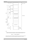
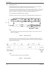
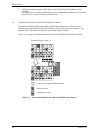
Each sector on the track consists of the following fields:
(1) Gaps (G1, G2, G3)
No pattern is written on the gap field.
(2) PLO Sync
In this field, pattern X'00' is written.
(3) Sync Mark (SM1, SM2)
In this field, special pattern is written. This special pattern indicates the beginning of the data field.
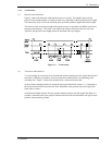
(4) Data field (DATA1-DATA4)
User data is stored in the data field of the sector. The length of the data field is equal to that of the
logical data block which is specified with a parameter in the MODE SELECT command. Any
multiple of 4 between 512 and 528 bytes can be specified as the length.
(5) BCRC
It is a 4-byte error detection code. Single burst errors with lengths of up to 32 bits for each logical
block can be detected.
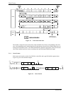
(6) ECC
This is the 400 bits code that allows detection and correction of errors in the data field, which is
capable of correcting the single burst error up to 200 bits max. on the fly.
(7) PAD
A specified length of x'00' pattern is written in this field. This field includes the variation by rotation
and circuit delay till reading/writing.