45
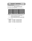
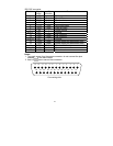
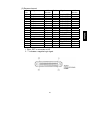
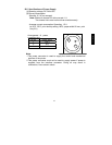
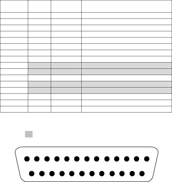
RS-232C connector
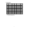
Pin No. Signal
name
I/O
direction
Function
1 FG -- Frame ground
2 TXD Output Send data
3 RXD Input Receive data
4 RTS Output Send request
5 CTS Input Send permission
6 DSR Input Data set ready
7 SG -- Signal ground
8 to 12 N.C. -- Unused
13 SG2 Input +24 V ground
14 SG2 Input +24 V ground
15 to 17 N.C. -- Unused
18 +24V Input Power supply for mechanism drive
19 +24V Input Power supply for mechanism drive
20 DTR Output Data terminal ready
21 to 24 N.C. -- Unused
25 INIT Input Forced reset
Notes:
1. To supply power from the power connector, do not connect the pins
shaded( )in the above table.
2. Use inch- screws to secure the connection.
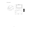
Connecting side
13 12 11 10 9 8 7 6 5 4 3 2 1
25 24 23 22 21 20 19 18 17 16 15 14


