


14
CHAPTER 2 HARDWARE CONFIGRATION
2.1 CPU
• This section describes the memory space and register composing CPU hardware.
■
Memory Space
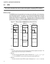
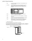
The MB89990 series of microcontrollers have a memory area of 64K bytes. All I/O, data areas,
and program areas are located in this space. The I/O area is at the lowest address and the data
area is immediately above it. The data area may be divided into register, stack, and direct-
address areas according to the applications. The program area is located near the highest
address and the tables of interrupt and reset vectors and vector-call instructions are at the
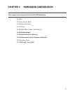
highest address. Figure 2.1-1 "Memory Space of MB89990 Series of Microcontrollers" shows
the structure of the memory space for the MB89990 series of microcontrollers.
Figure 2.1-1 Memory Space of MB89990 Series of Microcontrollers
• I/O area
• This area is where various resources such as control and data registers are located. The
memory map for the I/O area is given in APPENDIX A .
• RAM area
• This area is where the static RAM is located. Addresses from
0100
H
to
017F
H
(
0100
H
to
013F
H
for the MB89997) are also used as the general-purpose register area.
• ROM area
• This area is where the internal ROM is located. Addresses from
FFC0
H
to
FFFF
H
are also
0000H
0080H
00C0H
0100H
0140H
8000H
FFFFH
Mask ROM
Register
MB89997
I/O
0000H
0080H
0100H
0180H
C000H
FFFFH
RAM
MB89P195
Program PROM
(Mask ROM)
I/O
0000
H
0080H
0100H
0180H
8000H
FFFFH
MB89PV190
Vacant area
Vacant area
Vacant area
Register
RAM
External ROM
Vacant area
RAM
I/O
Register