


16
CHAPTER 2 HARDWARE CONFIGRATION
■
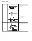
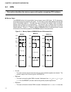
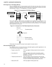
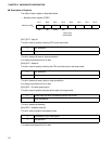
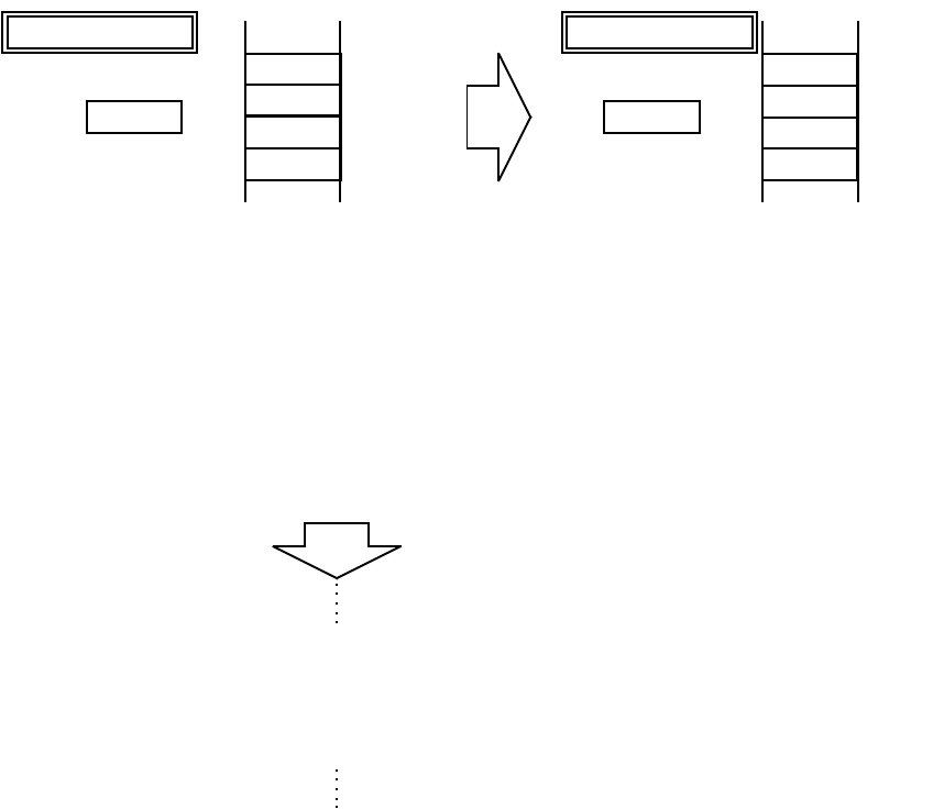
Arrangement of 16-bit Data in Memory
When the MB89990 series of microcontrollers handle 16-bit data, the data written at the lower
address is treated as the upper data and that written at the next address is treated as the lower
data as shown in Figure 2.1-2 "Arrangement of 16 bit Data in Memory".
Figure 2.1-2 Arrangement of 16 bit Data in Memory
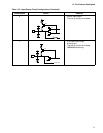
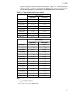
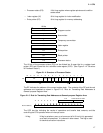
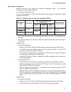
This is the same as when 16 bits are specified by the operand during execution of an
instruction. Bits closer to the OP code are treated as the upper byte and those next to it are
treated as the lower byte. This is also the same when the memory address or 16-bit immediate
data is specified by the operand.
Figure 2.1-3 Arrangement of 16-bit Data during Execution of Instruction
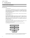
Data saved in the stack by an interrupt is also treated in the same manner.
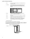
■
Internal Registers in CPU
The MB89990 series of microcontrollers have dedicated registers specified applications in the
CPU and general-purpose registers in memory.
MOVW ABCDH, A
34H
12H
ABCFH
ABCEH
ABCDH
ABCCH
1234H
A
ABCFH
ABCEH
ABCDH
ABCCH
1234H
A
Memory
After execution
Before execution
Memory
[Example]
MOV A, 5678
H ; Extended address
Assemble
XXXXH XX XX
XXXX
H 60 56 78 ; Extended address
XXXX
H E4 12 34 ; 16-bit immediate data
XXXX
H XX
• Program counter (PC) 16-bit long register indicating location where instructions
stored
• Accumulator (A) 16-bit long register where results of operations stored
temporarily. The lower byte is used to execute 8-bit data
processing instructions.
• Temporary accumulator (T) 16-bit long register where the operations are performed
between this register and the accumulator. The lower byte
is used to execute 8-bit data processing instructions.
• Stack pointer (SP) 16-bit long register indicating stack area