


34
CHAPTER 2 HARDWARE CONFIGRATION
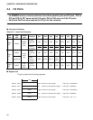
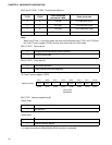
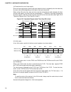
[Bit 3 and 2] T1CS1, T1CS0: Clock source select bit
Note:
When using Timer 1 in the 8-bit mode, the clock source selection bits (T1CS1 and T1CS0) of
the Timer 2 control register (T2CR) must be set to other than the 16-bit mode.
[Bit 1] T1STP: Timer-stop bit
[Bit 0] T1STR: Timer-start bit)
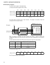
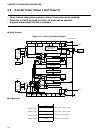
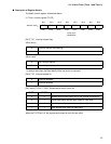
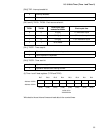
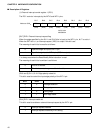
(2) Timer 2 control register (T2CR)
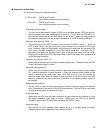
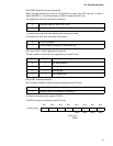
[Bit 7] T2IF: Interrupt request flag bit
(When write)
(When read)
1 is always read when the Read Modify Write instruction is executed.
T1CS1 T1CS0
Clock cycle time
selected at 4 MHz
Clock cycle time
00 2.0 [
µ
s]
×
2 instruction cycle
0 1 32.0 [
µ
s]
×
32 instruction cycle
1 0 512 [
µ
s]
×
512 instruction cycle
1 1 External clock
0 Counting continued without clearing counter
1 Counting suspended
0 Terminates operation
1 Clears counter and starts operation
Bit 7 Bit 6 Bit 5 Bit 4 Bit 3 Bit 2 Bit 1 Bit 0
Address: 0018
H
T21F T21E — — T2CS1 T2CS0 T2STP T2STR
(R/W) (R/W) (R/W) (R/W) (R/W) (R/W) (R/W) (R/W)
Intilial value
X00000X0
B
0 Interrupt request flag clearing
1 No operation
0 No interrupt request
1 Interval interrupt request