


32
CHAPTER 2 HARDWARE CONFIGRATION
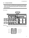
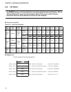
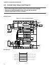
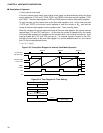
2.5 8/16-bit Timer (Timer 1 and Timer 2)
• Three internal clock pulses and one external clock pulse can be selected.
• Operation in 8-bit 2-ch mode or 16-bit 1-ch mode can be selected.
• A square-wave output function is included.
■
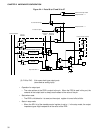
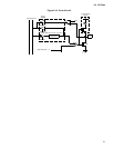
Block Diagram
Figure 2.5-1 8/16-bit Timer Block Diagram
■
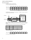
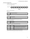
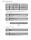
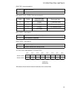
Register List
IRQ3
Square-wave
output initialization
pin control
R.S
Q
TFF
P34/TO
/INT00
Internal data bus
MPX
8-bit counter
CK
CLR
CO
Comparator
EQ
Compare data latch
LOAD
Data register
Data register
Compare data latch
LOAD
Comparator
EQ
T2STR T2STP T2CS0 T2CS1 — — T2IE T2IF
8-bit counter
CLR
CK
1/4
1/64
1/1024
Prescaler
MPX
P33/EC
CLR
CPU clock
1/4
1/64
1/1024
CLR
Prescaler
CPU clock
IRQ4
T1STR T1STP T1CS0 T1CS1 T1OS0 T1OS1 T1IE T1IF
Address: 0018H
Address: 0019H
Address: 001AH
Address: 001BH
T2CR
T1CR
T2DR
T1DR
8 bit
R/W Timer-2 control register
R/W Timer-1 control register
R/W Timer-2 data register
R/W Timer-1 data register