


40
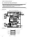
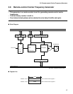
CHAPTER 2 HARDWARE CONFIGRATION
■
Description of Registers
(1) External-interrupt control register 1 (EIC1)
The EIC1 controls interrupts by the INT10 and INT11 pins.
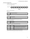
[Bit 7] EIR1: External-interrupt request flag
When the edge specified by the SL11 and SL10 bits is input to the INT11 pin, bit 7 is set to 1.
When the EIE1 bit is 1, an interrupt request (IRQ1) is output if this bit is set.
The meaning of each bit to be read is as follows:
1 is always read when the Read Modify Write instruction is read.
The meaning of each bit to be written is as follows:
[Bit 6 and 5] SL11, SL10: Edge-polarity select bit
This bit is used to control the input edge polarity of the INT11 pin.
[Bit 4] EIE1: Interrupt-enable bit
This bit is used to enable an external-interrupt request by the INT11 pin.
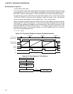
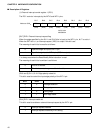
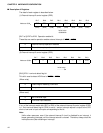
Bit 7 Bit 6 Bit 5 Bit 4 Bit 3 Bit 2 Bit 1 Bit 0
Address: 0023
H
EIR1 SL11 SL10 EIE1 EIR0 SL01 SL00 EIE0
(R/W) (R/W) (R/W) (R/W) (R/W) (R/W) (R/W) (R/W)
Intilial value
00000000
B
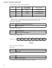
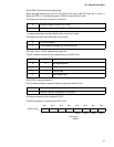
0 Specified edge not input to INT11 pin
1 Specified edge input to INT11 pin (IRQ1 is output.)
0 This bit is cleared.
1 This bit does not change nor affect other bits.
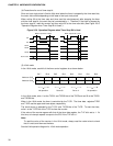
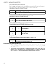
SL11 SL10
0 0 No edge detection
0 1 Rising edge
1 0 Falling edge
1 1 Both-edge mode
0 Interrupt request disabled
1 Interrupt request enabled by EIR1 setting