


Installation Requirements
3-18 C156-E228-02EN
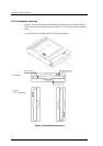
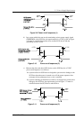
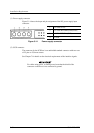
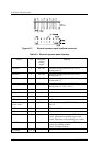
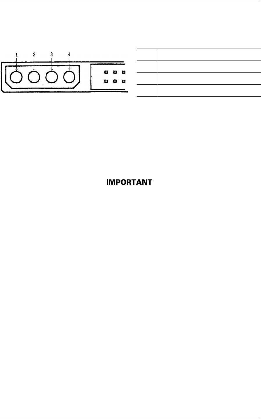
(1) Power supply connector
Figure 3.14 shows the shape and pin assignment of the DC power supply input
connector.
1 +12 VDC or N.C.
2 +12 VDC RETURN (GND) or N.C.
3 +5 VDC RETURN (GND)
4 +5 VDC
Figure 3.14 Power supply connector
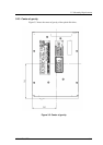
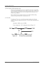
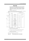
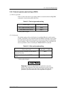
(2) SCSI connector
The connector for the SCSI bus is an unshielded standard connector with two rows
of 25 pins on 2.54 mm centers.
See Chapter 7 for details on the electrical requirements of the interface signals.
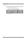
For cables using pin 01 as shield ground, note that the shield of the
connector on the drive is not connected to ground.