


C141-E116-01EN4 - 12
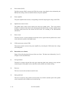
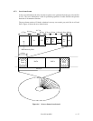
4.6.4 Synthesizer circuit
The drive uses constant density recording to increase total capacity. This is different from the
conventional method of recording data with a fixed data transfer rate at all data area. In the
constant density recording method, data area is divided into zones by radius and the data transfer
rate is set so that the recording density of the inner cylinder of each zone is nearly constant. The
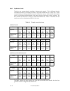
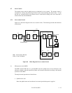
drive divides data area into 15 zones to set the data transfer rate. Table 4.1 describes the data
transfer rate and recording density (BPI) of each zone.
Table 4.1 Transfer rate of each zone
MPG3307AH-E
Zone 01234567
Cylinder 0
to
2207
2208
to
4223
4224
to
7231
7232
to
9823
9824
to
13119
13120
to
15615
15616
to
17087
17088
to
19359
Transfer rate
[MB/s]
49.73 48.87 47.22 45.79 43.61 41.88 41.01 39.28
Zone 8 9 10 11 12 13 14
Cylinder 19360
to
22047
22048
to
23839
23840
to
25247
25248
to
26591
26592
to
28767
28768
to
30175
30176
to
30783
Transfer rate
[MB/s]
37.22 35.77 34.62 33.45 31.43 30.12 27.92
MPG3204AH-E / MPG3409AH-E
Zone 01234567
Cylinder 0
to
2783
2784
to
5567
5568
to
8351
8352
to
11263
11264
to
13439
13440
to
16095
16096
to
17983
17984
to
19839
Transfer rate
[MB/s]
60.71 60.71 60.71 60.71 59.22 56.86 54.90 52.94
Zone 8 9 10 11 12 13 14
Cylinder 19840
to
22175
22176
to
23583
23584
to
25087
25088
to
26719
26720
to
28575
28576
to
29951
29952
to
30783
Transfer rate
[MB/s]
50.35 48.82 47.06 45.10 42.75 40.94 38.04
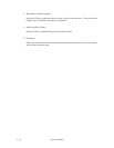
The MPU transfers the data transfer rate setup data to the RDC that includes the time base
generator circuit to change the data transfer rate.