


C141-E116-01EN5 - 16
5.3.2 Command descriptions
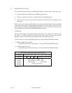
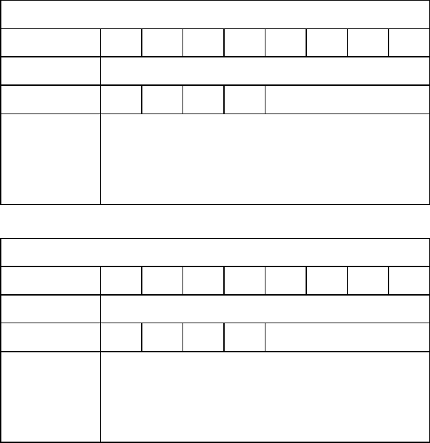
The contents of the I/O registers to be necessary for issuing a command and the example indication
of the I/O registers at command completion are shown as following in this subsection.
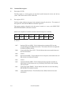
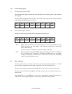
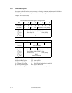
Example: READ SECTOR(S)
At command issuance (I/O registers setting contents)
Bit 76543210
1F7
H
(CM) 00100000
1F6
H
(DH)
×
L
×
DV Head No. / LBA [MSB]
1F5
H
(CH)
1F4
H
(CL)
1F3
H
(SN)
1F2
H
(SC)
1F1
H
(FR)
Start cylinder address [MSB] / LBA
Start cylinder address [LSB] / LBA
Start sector No. / LBA [LSB]
Transfer sector count
xx
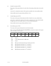
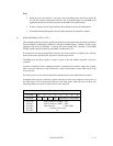
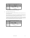
At command completion (I/O registers contents to be read)
Bit 76543210
1F7
H
(ST) Error information
1F6
H
(DH)
×
L
×
DV End Head No. / LBA [MSB]
1F5
H
(CH)
1F4
H
(CL)
1F3
H
(SN)
1F2
H
(SC)
1F1
H
(ER)
End cylinder address [MSB] / LBA
End cylinder address [LSB] / LBA
End sector No. / LBA [LSB]
X‘00’
Error information
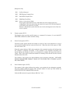
CM: Command register FR: Features register
DH: Device/Head register ST: Status register
CH: Cylinder High register ER: Error register
CL: Cylinder Low register L: LBA (logical block address) setting bit
SN: Sector Number register DV: Device address. bit
SC: Sector Count register x, xx: Do not care (no necessary to set)