


5
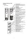
Component Names and Their
Functions
Front Panel
Rear Panel
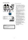
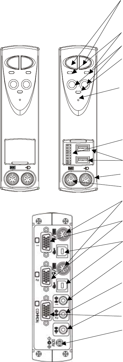
1. PC Select Switch
Press this switch to select the host. PCs with
POWER LEDs out can also be selected if power
is being supplied to the switch device (one or
more host is ON).
2. Select LED
Lights up when the host is selected.
3. POWER LED
Lights up when the host is ON.
4. LOW POWER LED
The switch device monitors whether or not the
power voltage is normal. Connect the special AC
adapter when this LED lights.
5. Reset Switch
Normally, this switch is not used. Use this switch
when selection is not possible or when keyboard
or mouse cannot be operated. Gently push in by
the tip of a pointed object such as a propelling
lead pencil. Pressing this switch returns the
switch device to its initial state, and hosts can be
restored without being rebooted.
6. DIP Switches
These switches are used for selecting Hot Keys
and setting the layout of the keyboard in use.
7. HUB Port Connector
This connector is for connecting USB devices.
8. Mouse Connector (console)
Attach the mouse here.
9. KB Connector (console)
Attach the keyboard here.
10. KB/Mouse Connector
Connect this to the keyboard or mouse (PS/2)
port on the host with the special cable.
11. Monitor Connector
Connect this to the monitor port on the host with
the special cable.
12. USB Connector
Connect this to the USB port on the host with the
special cable.
13. Audio Connector IN1
Connect this to the PC’s Line Out jack.
(Do not attach to the PC’s Speaker Out jack)
14. Audio Connector IN2
Connect this to the PC’s Line Out jack.
(Do not attach to the PC’s Speaker Out jack)
15. Audio Connector Out
Connect this to the speaker.
16. Monitor Connector
(console)
Attach the monitor here.
17.
DC5V Connector
Attach the special AC adapter here.