


APPENDIX A: Server Specifications
66
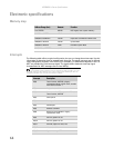
Electronic specifications
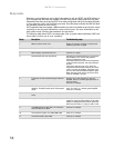
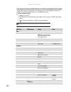
Memory map
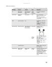
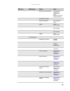
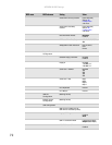
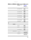
Interrupts
The following table reflects a typical configuration, but you can change these interrupts. Use this
information to determine how to program each interrupt. The actual interrupt map is defined
using configuration registers in the ICH5-R (I/O controller). I/O Redirection Registers in the I/O
APIC are provided for each interrupt signal. The signals define hardware interrupt signal
characteristics for APIC messages sent to local APIC(s).
I
Address Range (hex) Amount Function
0 to 07FFFFh 640 KB DOS region, base system memory
0A0000h to 0BFFFFh 128 KB Video or SMM memory
0C0000h and 0DFFFFh 128 KB Expansion card BIOS and buffer area
0E0000h to 0FFFFFh 128 KB System BIOS
0E0000h to 0EFFFFh 2 MB Extended system BIOS
FC000000h to FFFFFFFFh 64 MB PCI memory space
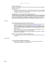
Important
If you disable an IDE controller to free the interrupt for that controller, you must
physically unplug the IDE cable from the system board. Simply disabling the drive by
configuring the BIOS does not make the interrupt available.
Interrupt Description
IRQ0 Timer/counter, HPET #0 in legacy
replacement Mode. In APIC mode, cascade
from 8259 controller 1
IRQ1 Keyboard controller
IRQ2 Slave controller INTR output. In APIC mode
Timer/counter, HPET #0
IRQ3 Serial port A
IRQ4 Serial port B
IRQ5 Parallel port
IRQ6 Diskette controller
IRQ8 Real-time clock/HPET#1 in legacy
replacement mode
IRQ9 Generic, Option for SCI
IRQ10 Generic, Option for SCI
IRQ11 HPET #2, option for SCSI, TCO
IRQ12 Mouse controller
IRQ13 System interrupt/FERR