


g
GE
OPM_SGS_USM_10K_40K_0US_V010.doc 11/88 Operating Manual
SG Series
10, 20, 30 & 40 kVA
3 DESCRIPTION
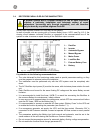
3.1 BLOCK DIAGRAM AND MAIN ELEMENTS
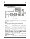
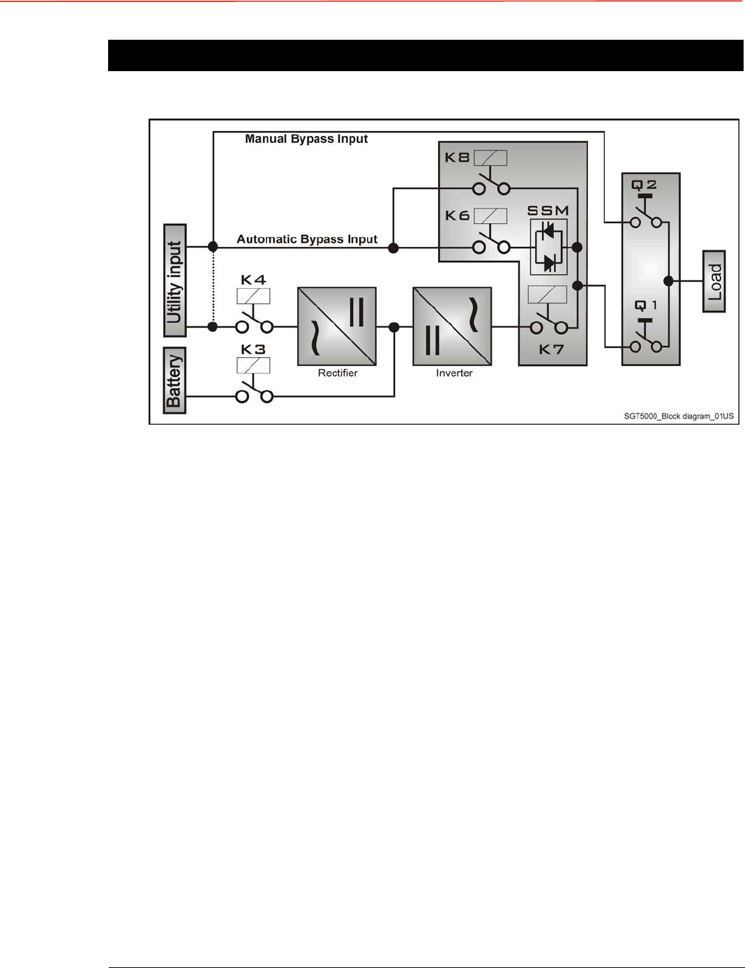
Fig. 3.1-1 Block diagram
The SG Series system can be divided into the following main elements:
Control System SG Series is designed with microprocessor-controlled signal
processing circuits. The interface between the operator and the unit is provided by the
monitoring system on the front panel.
This monitoring system consists of an active mimic diagram, a keyboard and a backlit
display.
Rectifier The standard Rectifier consists of a 6-pulse SCR-bridge, which
converts the 3-phase Utility Voltage into a controlled and regulated DC-voltage.
This regulated DC-voltage is used to supply power to the Inverter, and to provide charging
power to the Battery.
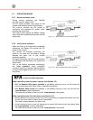
Inverter
The Inverter converts the DC voltage into a three-phase AC-
voltage with constant amplitude and frequency, which is completely independent and isolated
from the AC-input voltage.
Automatic Bypass The Automatic Bypass consists of a static semiconductor-switch
(SSM: Static Switch Module), used to provide an uninterrupted transfer of the Load from
Inverter to Utility.
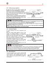
Back-feed Protection
All SG Series UPS's are equipped with an automatic system for
the protection against voltage back feeding towards Utility, through the Bypass (Applied
Standard IEC 62040-1).
This protection works automatically by opening contactor K6 and K8 (in series with the
thyristors of the static switch) and eventually K7, and acts in case of internal defects of the
system, or due to wrong manipulations on the Manual Bypass Q2.
Manual Bypass The Manual Bypass consists of a pair of manual switches (Q1
and
Q2)
, which removes the UPS from the Load for maintenance, while still supplying the
Load with power directly from the Utility.
Battery The Battery supplies the DC power to the Inverter when the
Utility is out of accepted tolerances.