


g
GE
OPM_SGS_USM_10K_40K_0US_V010.doc 84/88 Operating Manual
SG Series
10, 20, 30 & 40 kVA
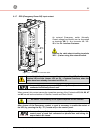
9.4 CONNECTION FOR OPTIONS
The installation and cabling of the options must be performed a qualified
service person.
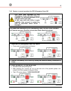
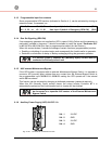
9.4.1 Remote Signaling Box (RSB)
The optional Remote Signaling Box allows monitoring of the operation of the UPS, using the potential
free contacts fitted on the “P4 - Customer Interface Board“ of the UPS.
It can be used by simply putting the box on a desktop or on a wall or, removing the box, it can be
surface mounted.
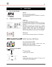
The remote panel contains an internal buzzer and the following status indicators:
• Mimic diagram with LED's indicating the operation of Rectifier and Inverter, and the power
source supplying the critical Load.
•
Alarm
(LED light and audible alarm) indicating a critical situation on the UPS.
•
Stop
indicating the UPS is preparing to shut down in a short time.
•
Mute
push button to reset the buzzer.
•
Test
push button checks all the LED’s and the buzzer of the remote panel.
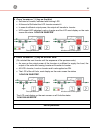
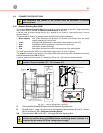
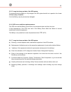
The cable connecting the RSB to the UPS cabinet must be min. 16 wires / 0.25mm
2
.
The plug B is included in the delivery of the option RSB (cable connecting UPS with RSB not included).
Maximal admitted length:
985 ft
(300 m).
It must be wired at one end with a D - female plug- 25 pin (J2 – P4 Customer Interface Board).
The alarms on free potential contacts can be connected on terminals X1
instead J2 (see correlation X1 – J2 in chapter 8.1).
Mute Test
max 985ft / 300m
yellow/brown
white/yellow
1
2
4
3
5
brown/green
7
6
8
10
9
11
white/green
blue/red
violet
grey/pink
13
12
14
16
15
17
yellow
green
brown
20
22
23
19
18
21
white
24
16
COMMON ALLARM
AUX. BUZZER
STOP OPERATION
20
22
23
17
19
38
LOAD ON MAINS
LOAD ON INVERTER
56
55
50
43
44
49
40
42
SIGNALLING
UTILITY FAILURE
GND
24V
34
37
33
32
31
X15
IM6544
1
2
J2 - SUB D - MALE
REMOTE
X3
X4
A
A
B -
P4 - IM0005
B
PLUG
J2
7
7
m
m
3
i
n
130mm
216mm
5 1/4" in
8 1/2" in
25
black
P.S.: The above mentioned colors are
XA
TERMINALS BLOCK
TERMINALS
XA
pink
red
blue
grey
pink
red
grey
blue
SUB D - MALE
suitables only for XY standard cable
S
G
T
5
0
0
0
_
O
P
T
_
0
1
0
-
1
5
0
_
R
M
S
_
0
1
U
S
1
12 13
2
14
3
15
4
16
5
17
6
18
7
19
8
20
9
21
10
22
11
1
14
9
1
21
1
2
3
4
1
2
3
4
J2
XA
BLOCK
BOX
Pink + Red
Grey + Blue
Stop
Alarm
g
GE Digital Energy
Customer Interface
2
1
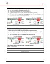
Fig. 8.4.1-1 Remote Signaling Box connection
A
Terminals
X3
,
X4
and
X15
fitted inside the Remote Signaling Box.
B Plug J2 (sub D - male - 25 pin) must be connected to the connector J2 (sub D - female-
25 pin) located on “P4 - Customer Interface Board“.
XA
Terminals block
XA
for 24 VDC / 1A supply Remote Signaling Box.
If the remote signal panel is plugged on connector J2, the terminal blocks X1
cannot be used to drive an external alarms monitoring device, because it is
supplied by the internal UPS low voltage power supply.