


g
GE
OPM_SGS_USM_10K_40K_0US_V010.doc 80/88 Operating Manual
SG Series
10, 20, 30 & 40 kVA
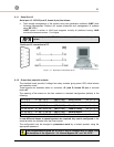
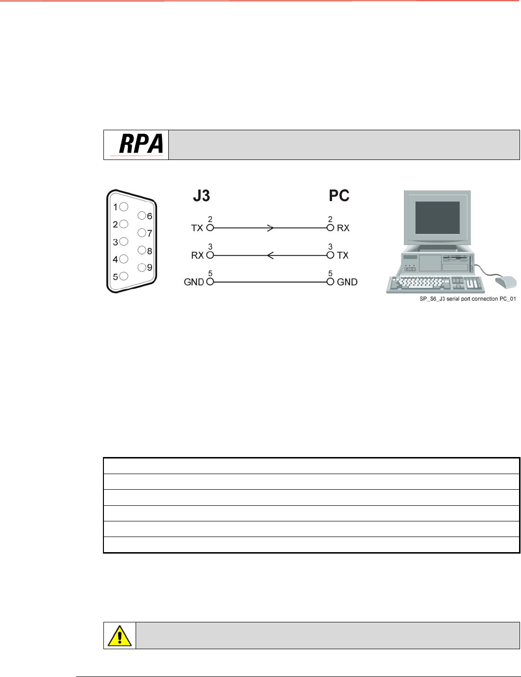
8.1.1 Serial Port J3
Serial port J3 - RS-232 (sub D, female 9 pin) that allows:
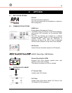
• Total remote management of the system using new generation software JUMP (Java
Universal Management Platform) for system protection and management of systems
using GE UPS’s.
JUMP system is written in JAVA and supports virtually all platforms having JAVA
runtime environment version 1.1 or higher.
The serial port J3 - RS-232 is enabled on all the units of the parallel
system.
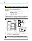
Serial port J3 connection to PC
Fig. 8.1.1-1 Serial port J3 connection to PC
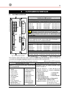
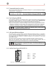
8.1.2 Output free potential contacts
The interface board provide 6 voltage free relay contacts giving some UPS critical alarms
and operation mode.
These signals are available either on connector
J2- (sub D, female 25 pin)
or terminal
blocks X1.
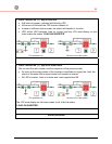
The meaning of the alarms on the free contacts in standard configuration (default) is the
following:
X1 / 1, 2, 3 or J2 / 1, 2, 3 (NO, C, NC) Utility Failure
(def. Par. RL=1)
X1 / 4, 5, 6 or J2 / 4, 5, 6 (NO, C, NC) Load on Inverter
(def. Par. RL=3)
X1 / 7, 8, 9 or J2 / 7, 8, 9 (NO, C, NC) Stop Operations
(def. Par. RL=5)
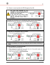
X1 / 12, 13, 14 or J2 / 14, 15, 16 (NO, C, NC) Load on Utility
(def. Par. RL=2)
X1 / 15, 16, 17 or J2 / 17, 18, 19 (NO, C, NC) General Alarm
(def. Par. RL=4)
X1 / 18, 19, 20 or J2 / 20, 21, 22 (NO, C, NC) Acoustic Alarm
(def. Par. RL=6)
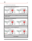
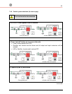
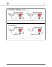
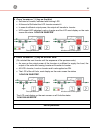
In case different alarms or operating status are required, they can be configured on the
same terminals via software from the control panel.
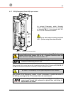
The configuration can be changed in parameters mode by a trained operator using the
appropriate password.
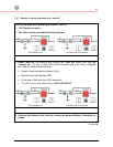
The programmable signals on X1 and J2 will be disabled with Q1 open, with
the exception of the signals for “16 - Manual Bypass ON” and “26 - EPO”.