


g
GE
OPM_SGS_USM_10K_40K_0US_V010.doc 82/88 Operating Manual
SG Series
10, 20, 30 & 40 kVA
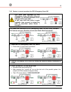
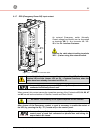
8.1.7 EPO (Emergency Power Off) Input contact
4
1
3
2
3
2
1
SGT5000_100-150_Customer interface EPO_01
4
XB
J2
JP3
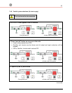
Fig. 8.1.7-1 Terminals for connection EPO
An external Emergency switch (Normally
Closed voltage-free contact) can be connected
on terminals XB / 1 - 4 or connector J2 / 12 -
25 of the P4 - Interface Customer.
Remove the cable short-circuiting terminals
XB 2 - 3) when using this external switch.
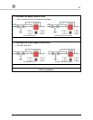
To enable this function, remove cable short-circuiting XB / 2 - 3 on the
Terminal XB and the Jumper JP3 on P4 – Customer Interface, when the
cables have been already connected on XB or J2.
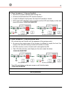
In a parallel system a separate NC (Normally Closed) contact must be
connected individually to each unit.
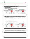
When opened, this contact causes the immediate opening of the Contactors
K3
,
K4
,
K6
,
K7
and K8, as well as the shutdown of Rectifier, Inverter and Static-Switch.
Be aware: The reliability of the system depends on this contact!
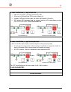
After closure of the Emergency contact, a reset is necessary to enable the restart of
the UPS, by pressing the key “O” (inverter off) on the control panel.
In case of a parallel system press the key “O” (inverter off) on the
control panel of each unit connected on parallel bus and having it’s
output switch Q1 closed.