


g
GE
OPM_SGS_USM_10K_40K_0US_V010.doc 21/88 Operating Manual
SG Series
10, 20, 30 & 40 kVA
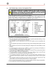
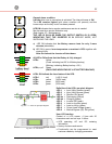
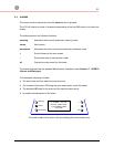
alarm
General alarm condition.
It blinks
when
one or more alarm is activated. The internal buzzer is
ON
.
The LED remains lighted (with alarm condition still present) and the
buzzer stops as the key “mute” has been pressed.
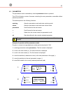
service check
LED ON indicates that a regular maintenance service is needed.
May be reset by a service technician only.
(See chapter 10 – Maintenance)
THE LED IS ON ALSO WHEN THE OUTPUT SWITCH Q1 IS OPEN,
INDICATING THAT THE INVERTER IS IN
SERVICE MODE
,
NOT
SUPPLYING THE LOAD.
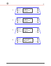
a) LED ON indicates that the Battery reserve lasts for only 3 more
minutes
(selectable).
b) LED ON in case of over temperature or overload >125% together with
missing
Utility
.
After the timeout the Inverter will shut down.
All LED’s ON indicate that the Battery is fully charged.
LED a Yellow
(Fixed: indicating last 25 % of Battery backup)
(Blinking: indicating Battery backup ≤ 5%)
LED b, c, d
Green
(EACH ONE INDICATING 25 % OF BATTERY BACKUP)
LED’s ON indicate the Load status of the UPS.
LED d red (≥100 % load)
LED c
yellow (100% load)
LED b green (66% load)
LED a
green (33% load)
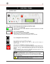
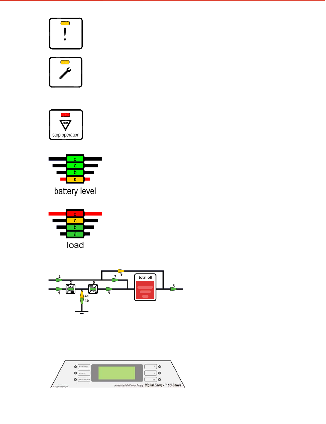
Fig. 5.2.1-1 LED’s on synoptic diagram
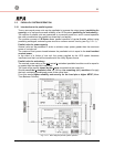
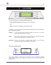
Definition of the LED’s on mimic diagram
LED 1 = Input Utility Rectifier (green)
LED 2 = Input Utility Bypass (green)
LED 3 = Rectifier ON (green)
LED 4a = Discharging (yellow)
LED 4b = Charging (green)
LED 5 = Inverter ON (green)
LED 6 = Load on Inverter (green)
LED 7 = Load on Utility (green)
LED 8
= Output Load Voltage (green)
LED 9 = Manual Bypass (Q2) ON (yellow)
Fig. 5.2.1-2 LCD screen
User LCD Interface
Consist of a LCD screen, 4 lines with 20
characters each and six keys. It offers:
• UPS operating, AC and DC metering
information.
• History of alarms and events.
• Functionality can be programmed to meet
customer needs by changing parameters.