


g
GE
OPM_SGS_USM_10K_40K_0US_V010.doc 65/88 Operating Manual
SG Series
10, 20, 30 & 40 kVA
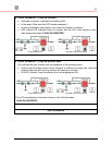
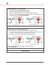
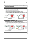
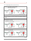
3. Connect the Battery to all Units by closing the external Battery Switches or
Fuses, in case of External Battery.
4. Press
“
inverter on
”
( I ) key on first Unit.
• Soft-start of Inverter, indicated with blinking LED.
• At the end of Soft-start the LED Inverter remains lit.
•
In case of sufficient output power, the output will transfer to Inverter.
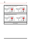
• UPS output LED indicates Load on Inverter and the LCD must display on the main
screen the status “
LOAD ON INVERTER
”.
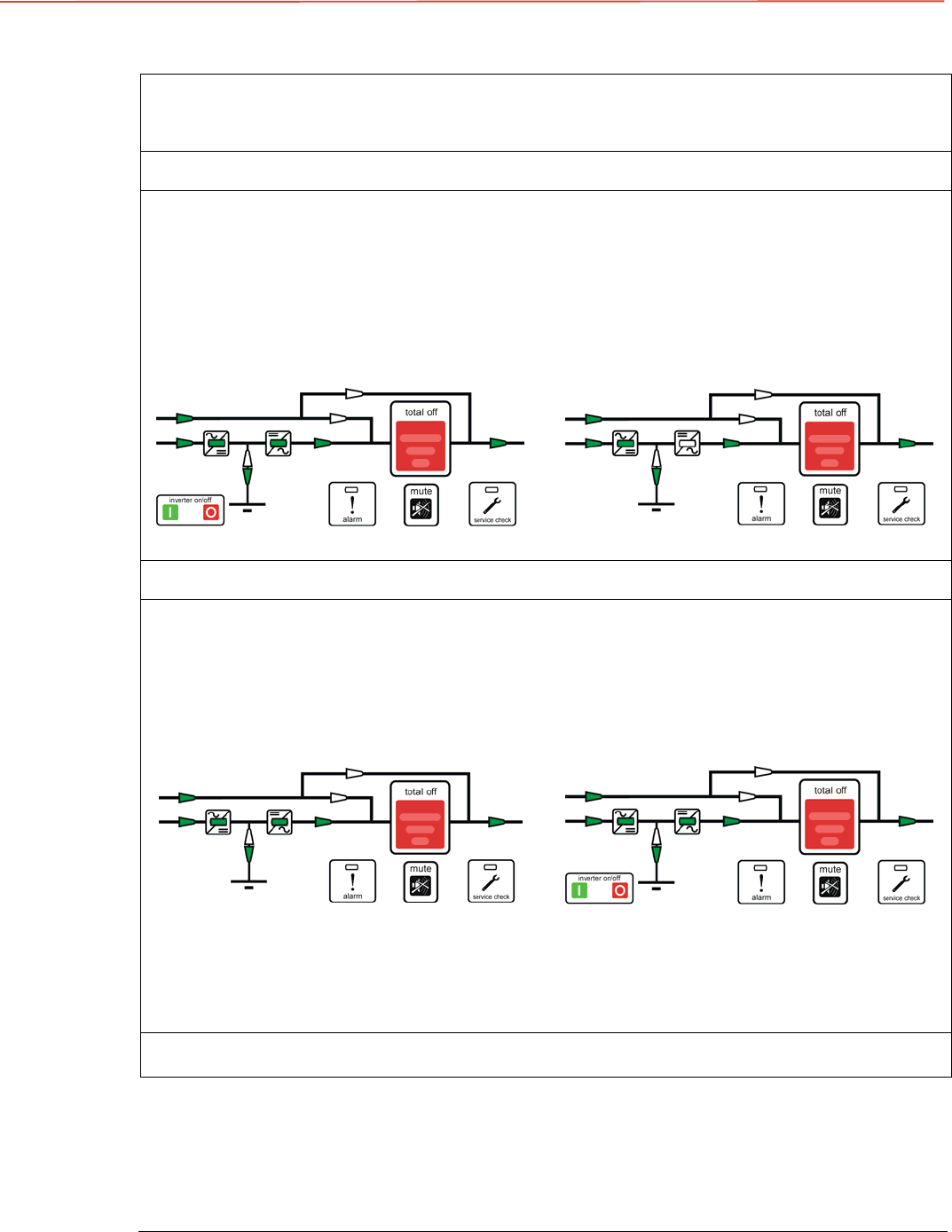
First operated unit All other units of the system
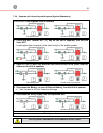
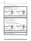
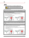
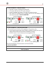
5. Press “inverter on” ( I ) key on all other Units.
(Do not start the next
Inverter
until the sequence of the previous ends).
• As soon as the output power of the Inverters is sufficient to supply the Load, the
output of the units with running Inverter will transfer to Inverter.
• All LED’s Inverter, Load on Inverter and Load supplied are ON.
First operated unit All other units of the system
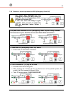
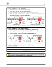
The LCD must display on the main screen on all Units the status
“LOAD ON INVERTER”.
End of procedure