


GFK-1425B Touch Display Products: IC752CTD400/450 7
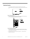
Installing ISA-Compatible Cards
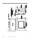
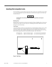
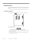
The Touch Display rear panel must be removed in order to gain access to the ISA bus cards. There
are six screws securing the rear panel. When these are removed, the rear panel can be lifted away
from the main unit.
Warning
Switch off the unit and disconnect the main power input before removing the
rear panel.
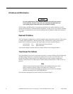
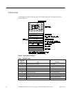
Blanking Plates
Blanking plates are installed on each unused card position. Remove blanking plates as necessary to
install new cards. Empty slots must always have a blanking plate installed, otherwise the air flow
through the unit will be affected.
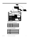
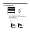
Card Clamp
A card clamp bracket, which can accommodate the two standard heights of ISA bus cards, is fixed
inside the rear panel. The card clamp bracket has nylon card-securing blocks fitted above each
vacant card position. When installing a full height card in one of these positions, remove the long
block from the appropriate position on the bracket and replace with a short block.
Full height cards — 114mm (4.5 inches) approx. — are secured by short nylon blocks
Low height cards — 100mm (3.9 inches) approx. — are secured by long nylon blocks
Figure 4. Card Clamp