


18
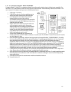
4.1 Standard Mounting Procedures
4 .1.1. As Service Equipment and/or primary Load Center Panel: Models ATS1001D/R, ATS2001D/R or ATS2002R:
When using the transfer switch as Service Entrance Equipment, mount the OVATION™ Series ATS as close as possible to the utility
meter.
NOTE on Models ATS1001R, ATS2001R and ATS2002R only (NEMA Type 3R enclosures): If conduit hub is required, purchase
separately from an authorized Siemens distributor, following directions provided. See product label on door/cover for list of hubs
available. See product label on door/cover for conduit hub part numbers. Punch appropriate size hub hole in Model ATS2002R
enclosure, all other enclosures have pre-punched hub holes. If a conduit hub will not be used, install included cover plate using
provided hardware.
1. Remove the cover and dead front from the OVATION™ Series ATS. Hold it level
against the mounting surface, mark and drill the mounting holes. If flush mounting,
locate between appropriate studs and secure properly. Required knockouts may be
removed prior to mounting.
2. Remove the cables plugged into the Control Module. Care should be taken in
unplugging these cables as they have a securing ‘latch’. Forcing the cables loose
will damage the connectors. Observe that the power mating plug J6 is installed in
the connector. Unplug it and set aside for future use in Section 4.3.
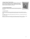
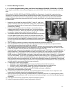
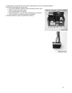
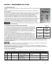
3. To avoid debris and metal chips from entering the Control Module, cover or remove
the Control Module from the panel, to remove, slide it towards the center of the
panel then lift the outside end to disengage it from the locking tabs in the base of
the panel, then pull the Control Module up to disengage it from the contacts on the
bus. Note: to install the Control Module, reverse the above removal instructions.
See Fig.4.1.1.3 FIGURE 4.1.1.3
4. Cover or remove the installed circuit breakers and associated mechanisms from dust and metal chips.
5. Fasten the OVATION™ Series ATS to mounting surface with appropriate fasteners (not provided); use spacers behind the
mounting holes to ensure the enclosure is plumb and not distorted.
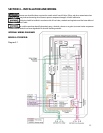
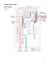
6. Install appropriately sized Utility and Generator source wire into the enclosure and use proper fittings to secure and provide
proper protection to conductor insulation. (For more information on wire size and ampacity ratings, see NEC Article 310, Table
310.16). The OVATION™ Series ATS have been UL Listed for use with Copper or AL wire.
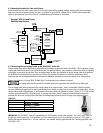
7. Connect the X and Y source wire to the appropriate circuit breaker terminals marked “UTILITY MAIN” or “GENERATOR MAIN”. If
optional PowerPause™ Load Management Modules are going to be installed, each X and Y generator source wire should pass
through the hole of current transformer on the current sense cable supplied with PowerPause Load Management module kit
BEFORE connection to GENERATOR MAIN circuit breaker. Route current sense cable as shown in diagrams 4.1 – 4.3, and plug P4
into J4 on Control Module. Ensure UTILITY and GENERATOR SENSE lead wires located in UTILITY and GENERATOR MAIN circuit
breaker lugs remain in the UTILITY and GENERATOR MAIN lugs when tightening the UTILITY and GENERATOR MAIN source wire.
When AL conductors are used, the application of a UL-Listed conductor termination compound is recommended. Connect neutral
and ground source wires from the utility and generator to the corresponding NEUTRAL and GROUND bars. Refer to product label
on transfer switch for correct terminal tightening torque requirements.
8. If transfer switch is used as Service Equipment:
a. ATS1001D/R: Tighten “NEUTRAL BOND” green screw at top of right hand neutral bar into enclosure.
b. ATS2001D/R: Install “NEUTRAL BOND” kit provided, following Installation Instructions included with kit.
c. ATS2002R: Connect provided “NEUTRAL BOND” pigtail located on neutral buss to ground bus.
Apply provided “Service Disconnect” label next to the UTILITY MAIN circuit breaker on deadfront.
9. Install branch circuit breakers and wiring as required.
10. If transfer switch is installed in new construction, affix provided paint/plaster shield to transfer switch to keep interior clean.
Remove when all wallboard and painting is completed and proceed to next step.
11. Install and wire the correct type and rating of compatible branch circuit breakers (see Section 2.2), complying with the product
label wiring diagram for each branch circuit. See the branch circuit breaker markings for correct wire size and tightening torque
requirements.
12. Ensure all wires are clear of the actuator/motor module and mechanical interlocks.
13. Reinstall all components and cables if removed, and proceed to Section 4.2.
SLIDE
FIRST
THEN
PULL UP
HERE