


20
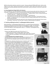
4.2 Mounting Procedure for Two Load Centers
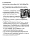
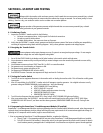
When the main service is 400A or more and/or 2 or more load centers will be installed, dedicate one load center to non-emergency
loads (not connected to generator power) and the 2
nd
load center as an OVATION™ Model 1001 or 2001D/R load center/transfer
switch for generator back-up circuits. Follow 4.1 Standard Mounting Procedures for installation.
4.3 Connecting the Low Voltage Cable to the OVATION™ Series ATS
The low voltage cable delivers important signaling information between the generator and the OVATION™ ATS for generator startup,
running and shutdown and powers the Control Module with the generator battery. Some generators utilize all four wires for signaling
while others use only three or two wires. Since no two generators are alike, the termination of the low voltage cable to the generator
will be different from manufacturer to manufacturer. Refer to the generator manufacturer’s installation instructions and visit
http://www.gen-tran.com/support/installation instructions for additional information for proper connection of low voltage wiring.
Three or four-conductor, UL listed, 300V, 18 AWG (Type TC recommended) wire minimum is required.
Low voltage wire cannot be installed in the same conduit as the generator wires UNLESS at least 300V rated.
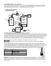
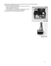
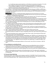
The low voltage cable will be terminated in the transfer switch on the control module. There is a small black 4-position terminal
connector (delivered plugged into J6 on the Control Module) that is labeled to indicate how to connect the low voltage cable. The low
voltage cable should be stripped about ¼” and inserted in the terminal block and tightened as shown in Figure 4.3. A 12 VDC contact
closure is provided between Pin 1&3 (close to run). If a voltage free contact closure is required to start/run/stop the generator,
terminate Pin 1&3 to the coil side of the ATSRK Relay Kit and terminate the primary side of the relay to the generator control.
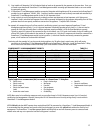
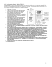
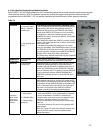
Table 4.3
PIN NUMBER on J6 FUNCTION
1 Ground (-12VDC)
2 Battery + (+12VDC)
3 ON/OFF (RUN)
4 Crank/Start
Note: Pin 1 is located towards the top of the Control Module.
IMPORTANT: The OVATION™ Series ATS is powered by the 12VDC battery located in the generator. The + and -12VDC MUST be
brought over from the generator. If the generator is a 2-wire control system, use a 3-wire conductor to ensure a -12VDC signal is
wired to the transfer switch on PIN 1. If 3-wire conductor is not available, install a jumper between PIN 1 and the ground bar in the
OVATION™ ATS.
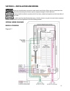
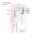
UTIL
400 Am
p
Meter
Ovation
™
ATS As Load Center
With 400 Amp Service
OVATION
™
ATS2001
or
ATS1001
Service Entrance
Load Center
EMERGENCY
LOADS
GEN
Load
Center
NON-EMERGENCY
LOADS
200 Amp
Disconnec
t
Furnace
Well Pump
Lighting
Refrigerator
Etc.
Control Module With
PowerPause™
Modules
Air
Conditioner
Compressor
Disconnec
t
PP1
PP2
PP3
PowerPause
™
Relay Box
Well
Pump
Control Wiring
Line Wiring
Non-Essential
Branch
Circuits
Etc.