


25
SECTION 6 –STARTUP AND TESTING
Voltages within the transfer switch enclosure present a shock hazard that can cause severe personal injury or death.
Use extreme caution to avoid touching electrical contacts when the cabinet door is open or removed. Do not wear jewelry or loose
clothing. Stand on a dry, non-conductive surface such as a rubber mat or wooden platform.
Improper operation of the generator presents multiple hazards that can cause severe personal injury or death.
Observe all of the safety precautions in your generator manuals.
6.1 Preliminary Checks
1. Inspect the OVATION™ transfer switch for the following:
• No loose or unconnected wires. Verify torques of all electrical connections.
• No tools or parts left inside cabinet.
• No debris inside cabinet. Use vacuum to clean out if present.
2. Verify that the OVATION™ transfer switch, generator and electrical power system of the house or building are compatible by
reviewing all equipment rating labels and wiring diagrams. Verify correct generator operation and voltage outputs.
6.2 Energizing the Transfer Switch
Severe equipment and property damage can occur if system is not energized at proper voltage. Do not energize
equipment if generator voltage does not match equipment rating labels.
1. Set to ON the UTILITY MAIN circuit breaker and all other breakers in the transfer switch and load center.
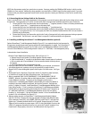
2. Use a voltmeter to measure utility-to-utility and utility-to-neutral voltages across the normal utility terminals to ensure utility
voltage is correct.
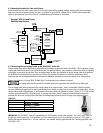
3. Use voltmeter to measure at least 13VDC from PIN 1 to PIN 2 on controller module.
4. Set generator main circuit breaker on Generator to ON.
5. Set generator main system switch/key to ON.
6. Set generator AUTO/MANUAL/OFF switch to AUTO.
7. Press SERVICE button. Generator start sequence will begin and runs for 5 minutes.
6.3 Testing the Transfer Switch
1. Turn OFF the service equipment disconnect in the transfer switch or feeding the transfer switch. This will simulate a utility power
interruption.
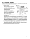
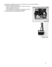
2. After a 5 second delay, the OVATION™ transfer switch will attempt to start the generator. Use a digital volt meter to verify
generator voltage at GENERATOR MAIN circuit breaker lugs. Verify the following:
a. UTILITY POWER LED 2 starts flashing.
b. UTILITY LOAD LED 1 turns off.
c. LOAD LED 3 flashes while the actuator is moving.
d. GENERATOR POWER LED 4 lights.
e. GENERATOR LOAD LED 5 lights.
3. Turn ON service disconnect that was turned OFF in Step 1 above. UTILITY POWER LED light stops flashing.
4. After a one-minute delay, the OVATION™ transfer switch will transfer loads back to utility power (UTILITY LOAD lights,
GENERATOR LOAD LED turns off, cool down and shut down generator (GENERATOR POWER LED turns off). Testing is now
complete.
6.4 Programming the PowerPause™ Load Management Modules (if installed)
PowerPause™ Load Management Modules require programming when first installed, added, deleted or moved, when the generator is
replaced, when load management priorities change and when the power requirements of the connected managed loads change (i.e.
replacing an A/C compressor with a smaller, larger or more efficient unit).
1. Prior to programming PowerPause™ Load Management Modules, complete the following:
a. Steps 4.5 and 5.1. Programming mode will not start unless PowerPause™ Load Management Modules are installed.
b. Turn OFF all branch circuit breakers in the transfer switch (or sub-panel powered by transfer switch) except for branch
circuit breakers powering managed loads. If multiple branch circuit breakers are required to power the managed load