


23
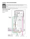
SECTION 5 – PROGRAMMING THE SYSTEM
5.1 Setting Generator Size
If PowerPause™ Load Management Modules are not installed, dial should be set to 25Kw. (Factory default setting
is 25Kw).
NOTE: Setting dial to 25Kw disables all power management functions even if PowerPause™ Load Management
Modules are installed.
If any PowerPause™ Load Management modules are installed and connected to manage loads, the generator size
needs to be set for proper operation. Referring to your generator Installation and Owners Manuals, determine the
net output of the generator (in Kw) accounting for fuel type, altitude, relative humidity and any other
manufacture’s suggested derating adjustments. If the net generator output exceeds 25Kw and PowerPause™
Load Management modules are installed and connected to manage loads, set GENERATOR SIZE to 22.5Kw.
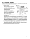
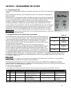
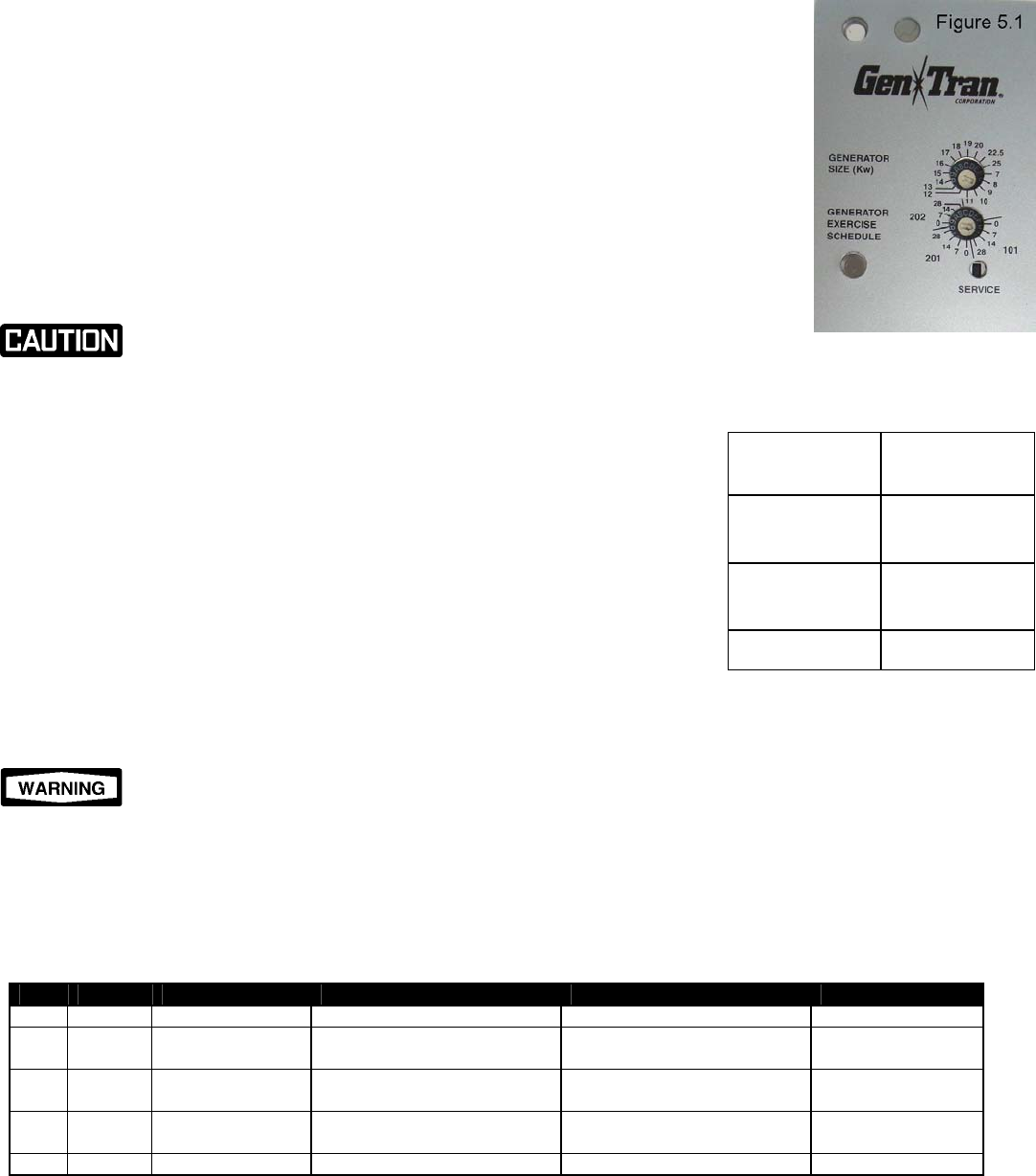
To set the generator size on the OVATION™ Series ATS, locate the GENERATOR SIZE dial on the User Display and
using the small straight blade screwdriver provided, rotate the dial arrow to the desired size, from 7 to 22.5Kw,
rounding down to not exceed the derated generator output. For example, if you determine that the derated
generator output is 19.5 Kw, set the GENERATOR SIZE dial to the next SMALLEST rating, 19Kw. See Figure 5.1.
Improperly setting the GENERATOR SIZE can permanently damage the generator, transfer switch
and loads connected to the transfer switch.
5.2 Setting Generator Exercise Schedule and Transfer Option
Each OVATION™ Series ATS has a generator exercise timer that will start and exercise the generator
at 0, 7, 14, or 28 day intervals (factory setting is 7 days). The transfer switch can also be programmed
to transfer loads to the generator during generator exercise (factory setting is NO load transfer). The
exercise cycle will last for approximately 15 minutes. If a utility power failure occurs during the
exercise cycle, the OVATION™ Series ATS will abort the generator exercise routine within 5 seconds,
and transfer the load to generator power.
To set generator exercise schedule to a setting other than the 7 days default, determine the
OVATION™ Series ATS model on the User Display where labeled “GENERATOR EXERCISE SCHEDULE”
and use provided small, straight blade screwdriver to rotate the dial to the desired schedule. See
Table 5.2 to determine model. Once set, the OVATION™ Series ATS will initiate a generator exercise
0, 7, 14 or 28 days from the exact time and day the dial is set. (See Figure 5.1) It is important to set
the GENERATOR EXERCISE SCHEDULE at the exact day and time you want the generator exercise procedure to occur. For example, if you set
the GENERATOR EXERCISE SCHEDULE dial to 14 on Thursday at 2:00 p.m., the OVATION™ ATS will initiate a generator exercise at 2:00 p.m.
on a Thursday, 14 days later. To change the time and day the generator exercise occurs, press the RESET button at the desired time and day
for the generator exercise to occur.
A “0” setting turns off ALL generator exercising initiated by the transfer switch. DO NOT use the “0” setting unless the
generator has a built-in exerciser that will continue to exercise the generator.
If transferring the load during generator exercise is required, on the User Display, press TRANSFER, then immediately press the SERVICE
switch. LED 5 flashes once when properly set. To set back to NO transfer during generator exercise, press TRANSFER, then immediately press
the SERVICE switch. LED 5 flashes twice when properly reset.
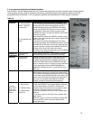
5.3 User Interface Display LEDs
The User Display has five (5) indicator LEDs that display the status of the power sources and loads on the OVATION™ Series ATS:
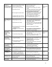
LED COLOR LABEL IF ON IF SLOW FLASHING IF FAST FLASHING
5 RED GENERATOR LOAD Load is powered by generator GEN MAIN circuit breaker error 2+5=service battery
4 RED GENERATOR POWER Generator power is within voltage
and frequency specifications
Generator power out of
specification
Generator start/stop
fault
3 YELLOW LOAD Power is energizing the Branch
Circuit Breaker Bus
Power source transferring Motor drive fault
2 GREEN UTILITY POWER Utility power is within voltage and
frequency specifications
Utility power out of specification 2+5= battery voltage
below 8VDC
1 GREEN UTILITY LOAD Load is powered by utility UTILITY MAIN circuit breaker error Bus not powered
Note: LEDs 1, 2 and 3 should be ON when loads are powered by the utility; LEDs 3, 4 and 5 should be ON when loads are powered by the generator.
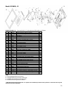
ATS2002R 202
ATS2001D
ATS2001R
201
ATS1001D
ATS1001R
101
MODEL
NUMBER
DIAL NAME
Table 5.2