


26
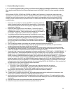
(i.e. air conditioning compressor and air handler fan), turn ON all branch circuit breakers for managed load. For installer
safety, 1 lighting circuit may be left ON to illuminate the transfer switch installation and/or egress areas.
c. Turn ON all appliances managed by a PowerPause™ Load Management Module. For air conditioning systems, set
thermostat to COOL and AUTO and low enough to close the 24VAC thermostat control circuit. For electric hot water
heaters, turn UP the thermostat to keep the heating elements on.
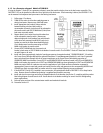
3. Enter PowerPause™ Load Management Module
learning
mode by pressing and holding down the SERVICE and RESET button
until all LEDs flash in numeric sequence. Release SERVICE and RESET buttons. If no Load Management Modules are detected, the
programming mode is terminated and the transfer switch resumes normal operation. NOTE: Exit
learning
mode at any time by
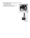
pressing RESET. See Figure 5.1.
All PowerPause™ Load Management Module programmed values are erased and reset to zero (0) when
entering
learning
mode. Exiting or terminating
learning
mode before values more than zero (0) have been stored will disable
PowerPause™ Load Management Module operation.
4. Generator will start, run for 15 seconds, stabilize output and transfer loads to generator power. The controller will automatically
detect each PowerPause™ Load Management Module installed and power off all managed loads.
5. LEDs1-5 will flash for 10 seconds. If you prefer to have the controller automatically
learn
the size of each managed load, continue
to step 6. NOTE: Entering the automatic
learning
mode will erase all previously
learned
loads from the controller memory. If you
need to change 1 or 2 loads, enter the manual
learning
mode instead. To enter the manual
learning
mode, press TRANSFER while
LEDs 1-5 are flashing and proceed to Step 10. NOTE: If LED flashing does not occur, reduce the safety lighting loads in Step
6.4.1.b until LEDs 1-5 start flashing.
6. LED 1 (GREEN) will begin slow flashing indicating the controller automatically detected a Load Management Module in position
1-2 and is ready to learn the size of priority 1 load. LED 1 will continue slow flashing for 20 seconds while Load 1 turns on and
runs. At the end of 20 seconds, the load will turn off.
7. If the load 1
learning
is successful, LED 1 will turn on for 5 seconds. If load 1
learning
is not successful (load exceeded 85% of
generator capacity or no load detected), LED 1 will fast flash for 5 seconds and the load is disqualified and not allowed to operate
on generator power. Note the LED fast flash condition.
8. Steps 5 -7 will be automatically repeated for each detected load. LED 1 & 5 will flash for priority 6 load.
9. When all detected loads have been
learned,
LEDs 1-5 turn on. Press RESET to terminate the automatic programming mode.
Automatic load
learning
is now complete. Go to Step 10 if disqualified loads from Step 7 require manual
learning
, otherwise go to
6.5.
10. Use the manual
learning
mode when the automatic
learning
in Steps 6-9 does not work or when existing learned loads require
changing. Refer to step 5 to enter manual learning mode.
11. The LED corresponding to the first installed load module will begin flashing. Press TRANSFER to scroll to the desired load to
learn
.
12. Press EXERCISE to start load
learning
for the selected load. The LED will light for 5 seconds, then slow flash for 20 seconds. If the
load
learning
is successful, the LED will turn on. If the load
learning
is not successful (load exceeds 85% of generator capacity or
no load detected), the LED will fast flash and the load is disqualified and not allowed to operate on generator power. Note the
LED fast flash condition. Press TRANSFER to scroll to the next load to learn & repeat Steps 12 as required. Press RESET to exit
manual
learning
mode.
13. If programming PowerPause Load Management Modules is still not successful, contact GenTran for assistance at 1-888-GEN-
TRAN.
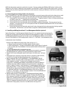
6.5 Re-Installing Covers and Labeling Circuits
1) Determine where branch circuit breakers have been installed and remove the required dead-front twist-outs. All dead-front
openings must be covered with circuit breakers or with filler plates. Order GenTran PN 51022 for additional filler plates.
2) Install dead front cover on enclosure with screws provided. For Models 1001 and 2001, any excess openings between circuit
breakers and twist out openings must be corrected by adjusting the two screws on the inside of door or adjusting the depth of the
box.
3) Apply circuit directory labels next to circuit breakers and identify each branch circuit. If the transfer switch is used as Service
Equipment, apply “SERVICE DISCONNECT” label next to the UTILITY MAIN circuit breaker. UTILITY MAIN and GENERATOR MAIN
are already labeled.
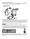
6.6 Generator Battery Monitoring
Generator battery failure is the most common cause for generator startup failure. The OVATION™ Series ATS monitors the battery
output during generator startup and if below minimum specifications, will continuously flash LED 2 and 5 alerting the user to further
test and service the generator battery. NOTE: Generator may not start if LEDs 2 and 5 are flashing.