


7
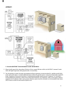
3) The transfer switch will automatically monitor if the generator has sufficient available capacity to operate any or all appliances
connected to PowerPause™ Load Management modules, starting with priority 1 Load, based upon appliance power requirements
“learned” from a setup utility at the time of the transfer switch installation. One or more PowerPause™ Load Management
connected appliances may operate simultaneously as long as the generator capacity utilization does not exceed 85%. If connected
load exceeds 85% of generator capacity, the OVATION™ ATS will begin power management, and will lock out those appliances
connected to the PowerPause™ Load Management modules in reverse priority order until the connected load is less than 85%.
Those appliances that are “locked out” by the transfer switch will stay “locked out” for 5 minutes before the transfer switch will
attempt to re-power the PowerPause™ connected appliances again.
4)
During the utility power failure, the generator will continue to power the load until it either runs out of fuel (gasoline, propane or
diesel-powered gensets) or until the utility power is restored.
WARNING! Do NOT refuel generator while it is running. Turn off the
Generator and allow it to cool down before refueling.
5) When the utility power has been restored, the generator will continue to power loads for 60 seconds to ensure utility power has
stabilized, then re-transfers the loads back to utility power.
6) The generator will continue to run without load for five minutes to cool down, and then is automatically shut off.
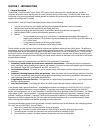
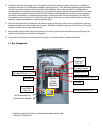
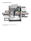
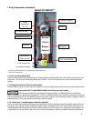
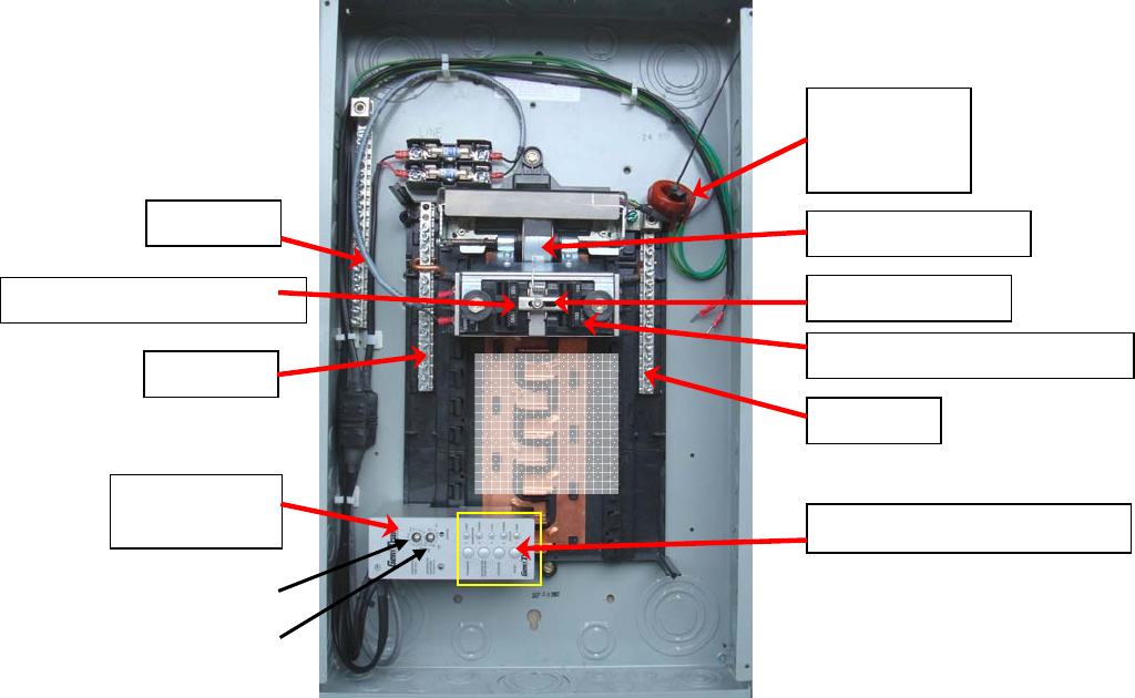
1.5 Key Components:
* Supplied with optional PowerPause™ Load Management Module (Model LSM)
** Not shown: ATSRK Relay Kit
Control Module
(Stabs onto
Actuator
(
See 1.5.3
)
Drive Motor Assembl
y
Ground Bar
Neutral Bar
Neutral Bar
[Branch
Circuit
Breaker
Spaces]
To Set Generator Siz
e
To Set Exercise Schedul
e
Model ATS1001D/R**
Generator Main 100 Am
p
(See 1.5.2)
Utilit
y
Main 100 Am
p
(
See 1.5.2
)
User Interface Display (See 1.5.1)
Current
Transformers*
(CT1
+
CT2)